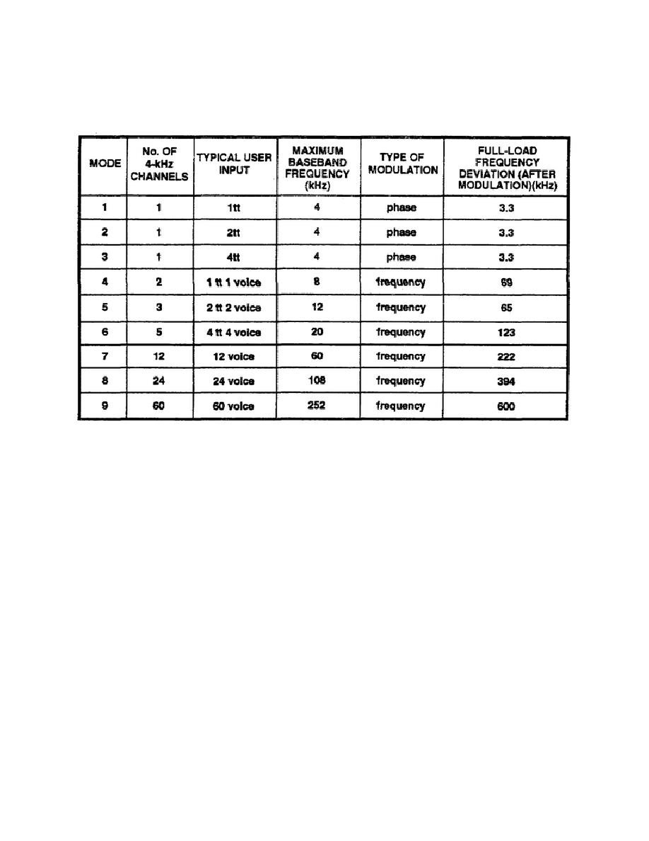
baseband frequency range that can be satisfactorily processed, and the type of modulation that will be
employed. An example of a nine-mode system is shown in Table 3-2.
Table 3-2. Operating modes.
3. Mode selection in the receiver involves the selection of appropriate filters, deemphasis circuits, output
circuits, and feedback circuits. The selected filters and circuits control the bandwidth of the receiver, which, in
turn, controls the number of channels that can be passed on to the terminal equipment.
4. Additional controls throughout the VF circuits are used to control the range of the baseband frequencies.
Compandor assemblies contain compressors and expandors-compressors for VF signals being transmitted and
expanders for signals being received. These circuits compress the dynamic range of the VF signals at the
sending end and expand the signals to their original condition at the receiving end.
SECTION V. RECEIVER CONTROL CIRCUITS
LEARNING EVENT 18: FREQUENCY-MODULATION FEEDBACK
1. Angle modulation is a technique used to achieve improvement factors greater than 1. This means that at the
receivers input the demodulated or baseband S/N is better (higher) than the C/N. For ordinary demodulation
(without feedback) of an angle-modulated signal, the C/N at the input must be greater than the moderately high
carrier-
SS0031
3-14


 Previous Page
