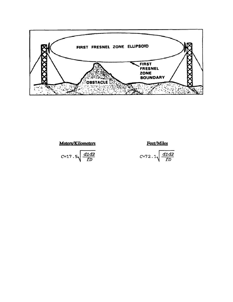
Figure 2-9. Fresnel zone
distance interval, draw a line which is at a right angle to the straight line. Continue this process
at each one-kilometer/one-mile interval for the entire straight line.
(3) Step 3 - Determine the required Fresnel zone clearance from the transmitting to
the receiving station by using the following formula:
Where:
C = Fresnel zone clearance in meters or feet
d1 = Distance from transmitting antenna to obstacle in kilometers or miles
d2 = Distance from obstacle to receive antenna in kilometers or miles
f = Frequency GHz
D = Total path distance in kilometers or miles between the two sites
(4) Step 4 - Using the elevation scale on the left margin of the graph paper for
reference, place a dot on the line which was drawn at a right angle to the straight line
corresponding to the required Fresnel zone clearance.
(5) Step 5 - Determine the required Fresnel zone clearance for each of the successive
right angle lines using the above formula.
(6) Step 6 - Place dots representing required Fresnel zone clearance for each
successive right angle line.
2-13
SS0121


 Previous Page
