to equalize for amplitude-frequency response calls for measuring the
level at the output of the amplifier. In this way, the equalizing
process will take into account line loss, equalizer loss, and
amplifier gain characteristic.
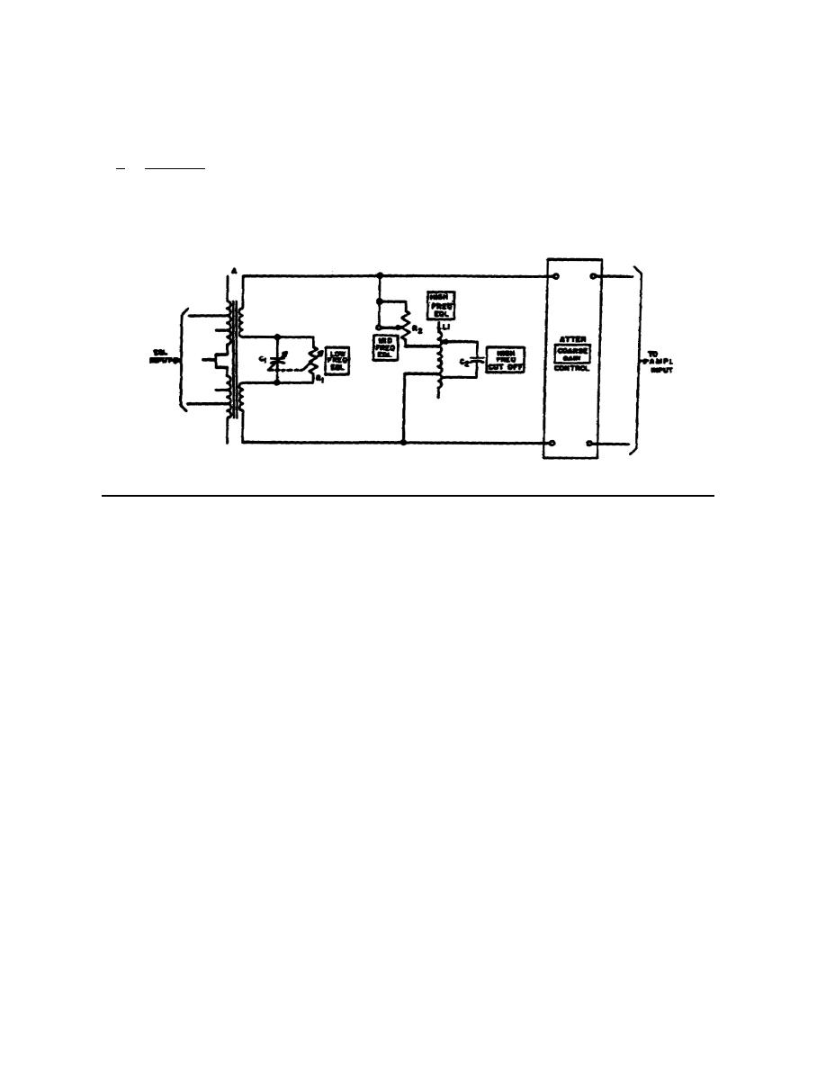
b. Circuit. An amplitude-frequency equalizer circuit (fig. 4-2) contains
two-basic circuits; one is for low-frequency, and the second is for high-
frequency equalization. The balance between the two circuits in the adjustment
process takes care of the frequencies which lie between the two limits; these
are called midfrequencies.
Figure 4-2.
Amplitude-frequency equalizer, simplified schematic diagram.
(1) Essentially, the equalizer circuit consists of a series-tuned
circuit (secondary winding of transformer A and capacitor C1) that
can be tuned to some frequency below the lowest line frequency. The
series-tuned circuit has little effect on the higher frequencies.
Resistor R1 adjusts the circuit Q, thus broadening the response as
needed.
Further, the low impedance of the tuned circuit near
resonance tends to pass the low frequencies more readily than high
frequencies, thus causing greater loss (dissipation) in resistors R1
and R2.
(2) A parallel-tuned circuit consisting of L1 and C2 is adjusted to
resonate at some frequency above the highest line frequency.
The
tuned circuit will therefore present highest impedance at the top
frequencies, but has little effect at the low frequencies. Resistor
R2 serves to lower the Q to the degree necessary to broaden the
response curve. The overlap of the broadened curves of both tuned
circuits determines the loss at midfrequencies.
(3) The combination of all adjustable elements in the equalizer produces
a variable-loss bandpass filter having cutoff frequencies below the
lowest frequency passed and above the highest frequency passed.
47


 Previous Page
