secondary (A, fig. 11) depends only on the varying component of the current in the primary, an alternating emf is induced
in the secondary. When a load, such as a meter or receiver, is connected to the secondary, and alternating current flows in
the secondary circuit.
20.
Structure of Carbon Transmitter.
a. B, figure 11, shows the front view and a
cross-sectional side view of a carbon transmitter. This
unit is one of several types in common use, all with a
similar basic structure. The path of current within the
unit is from the moving electrode, which is fastened to
the diaphragm, through the carbon granules, to the back
electrode. A bell-shaped carbon chamber is used so that
there is sufficient contact between the carbon granules
and the electrodes. Since the contact is uniform, and
operation is equally good in whatever position the
transmitter is held, this is called a nonpositional
transmitter. The moving front electrode exerts varying
pressure on the granules in accordance with the vibration
of the diaphragm, and the transmitter consequently is of
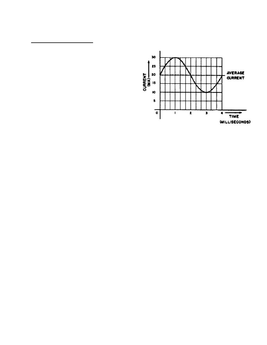
FIGURE 10. Current Versus Time
direct-action type. As the diagram shows, the moving
electrode is attached to the center of the conical
diaphragm, and forms the front center surface of the
carbon chamber.
b. The diaphragm is made of an aluminum alloy (B, fig. 11). Its thickness is .003 inch, and it has radial
ridges to increase its stiffness. Paper spacers, consisting of a number of thin paper rings, support the diaphragm at its
edge without interfering with its movement. The carbon chamber is closed on the front side by a silk covering,
clamped on the flange of the front electrode. A light, spoked, copper contact member, clamped under the front
electrode, provides a flexible connection between the front electrode and the metal frame. The stationary back electrode
is held in place in the frame by a threaded ring, and is insulated from the frame by a fiber washer and a ceramic
31


 Previous Page
