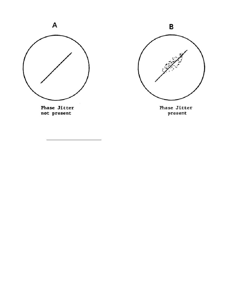
Figure 1-18.
Effect of phase jitter on lissajous pattern
oscilloscope display.
(2) Recording of test data. Test data will be recorded on the phase
jitter data sheet shown in figure 1-19.
Each station will record
measurements made on both send and receive sides of the circuit under test.
Analyzed data will be recorded in figure 3-3.
35


 Previous Page
