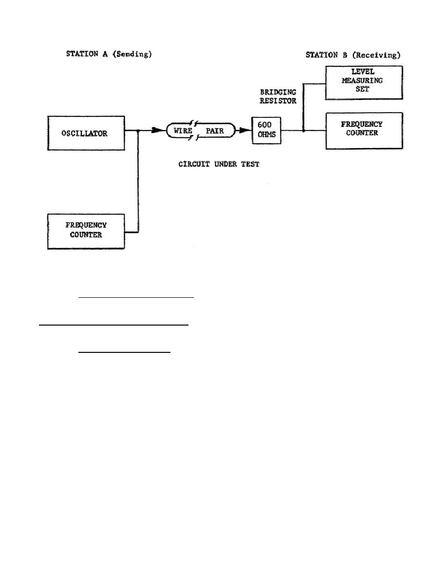
Figure 1-10.
Test arrangement for maximum change
in audio frequency, block diagram.
Readings obtained during the test are
recorded in the change in the audio-frequency data sheet, figure 1-11. Two
send station frequencies (1,000 and 2,000 Hz) are used. The entries in the
Max Permitted Frequency Change column in the data sheet are obtained from
the appropriate DCA parameter.
(1) At the sending station, tune the audio oscillator to 1.0 kHz.
Bridge the output terminals of the oscillator to the COUNTER INPUT terminal
of the 340B, with the control knob to the right of the input connector at
the COUNTER position.
The frequency counter insures that frequency is
within limits of 1/10 Hz. Set the oscillator to an output level equivalent
to 0 dBm0 at the TLP.
19


 Previous Page
