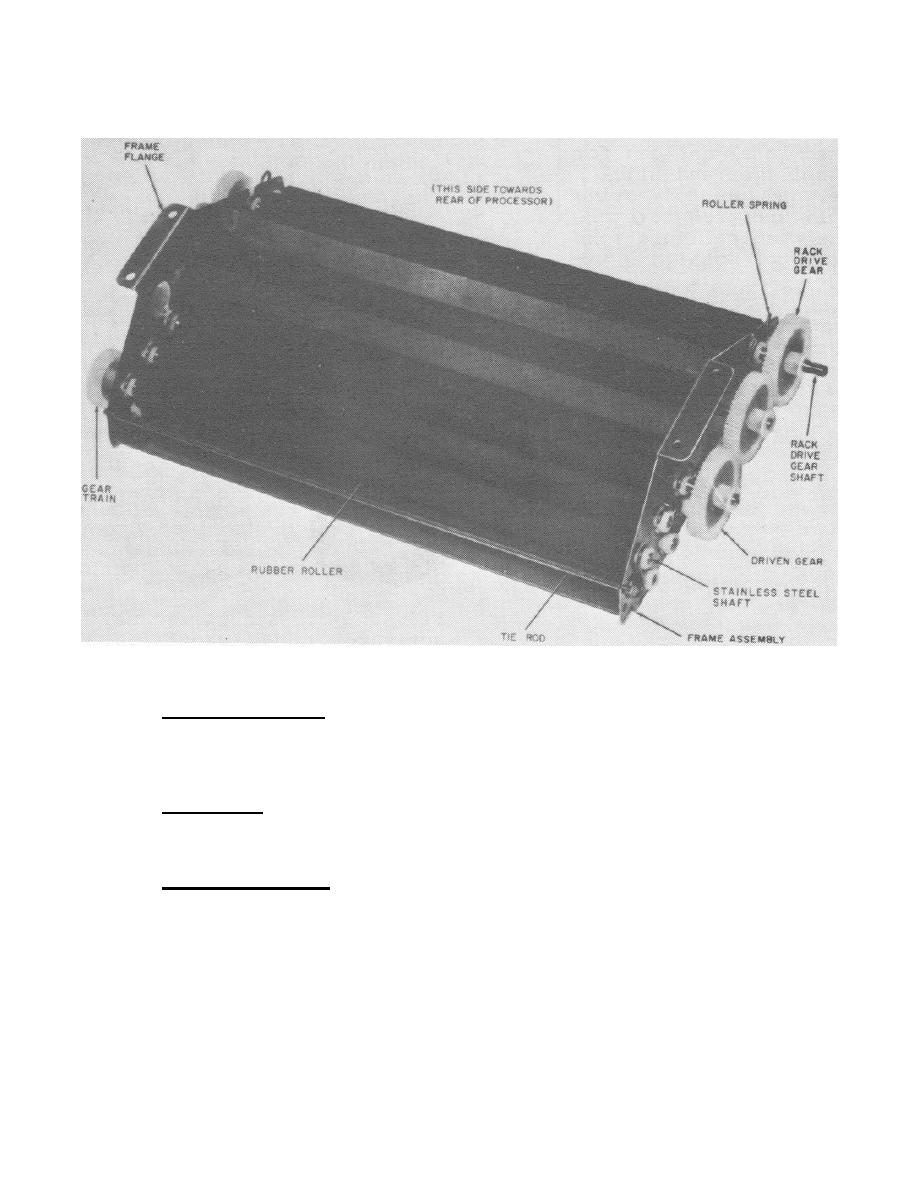
gear on the base assembly (figure 32), and is secured by the gear latch as
shown in figure 38.
FIGURE 34. Processing rack assembly.
e. Housing assembly. The plastic housing assembly (figure 31) fits
over the print processor, serving as a protective cover for the other
components and provides bottle holes for the activator and stabilizer
bottles.
f. Feed shelf. The feed shelf (figure 31) is a flat stainless steel
tray which attaches to the processing rack assembly, and provides a guide
for the exposed stabilization print into the print processor.
g. Valve assemblies. Two colorcoded plastic springloaded valve
assemblies (red for stabilizer and black for activator (figure 35) are used
to maintain the correct level of each solution in the solution tray (figure
33). Each valve assembly (figure 35 is screwed onto the top of its
corresponding stabilizer and activator chemical supply bottle (figure 311).
187


 Previous Page
