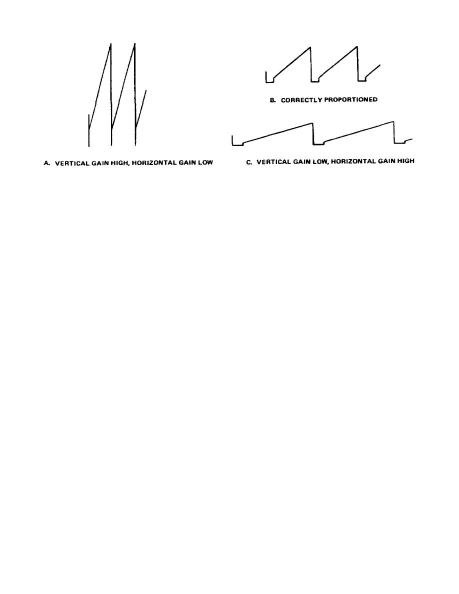
Figure 2-5a, b, and c.
Apparent changes in waveform with changes in vertical to
horizontal proportioning
(1) By contrast, if both the horizontal and vertical gain controls are
changed randomly so the change in the vertical direction predominates, the
characteristics of the trapezoidal waveform become masked.
(2) If you were inexperienced in the use of a scope, or if you had no
previous knowledge that the waveform was supposed to be a trapezoid, you could
reach the erroneous conclusion that the display was a sawtooth waveform.
On the
other hand, if you know that the circuit produces a trapezoidal wave and wish to
closely inspect the waveform for any irregularities, such proportioning of the
display is entirely acceptable and advisable.
(3) By changing the horizontal and vertical gain controls once more to the
opposite extreme so the display is exaggerated predominantly in the horizontal
direction, you produce a waveform like that shown in Figure 2-5c.
Under these
conditions, the trapezoidal waveform viewed on the scope screen could be
interpreted as a sawtooth waveform with excessive retrace time.
h. A height-to-width ratio of approximately 2 to 3 or 4 to 5 provides optimum
display proportions for general purpose waveform examinations.
Once you are
certain of the waveform you are inspecting, expansion or exaggeration of the
waveform in the vertical or horizontal direction to observe waveform irregularities
may be very advantageous.
i. Sometimes the signal at the point under examination is so small that a
display of more than a half-inch in the vertical dimension cannot be obtained. The
horizontal dimension of the display must also be reduced so that the display is
correctly proportioned. A reduction in beam intensity, followed by a refocusing of
the spot, generally produces a display which is easier to view.
42


 Previous Page
