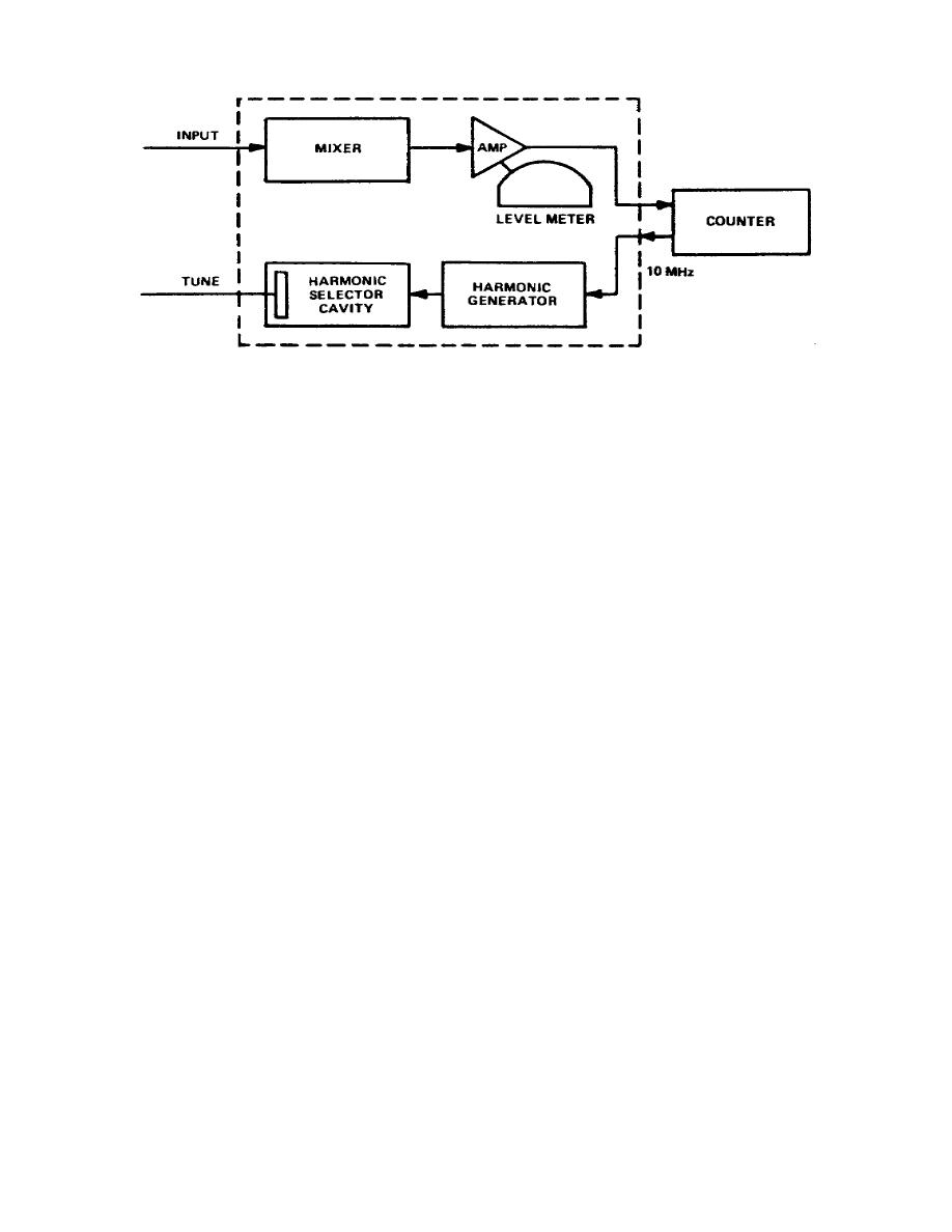
Figure 3-10.
Electronic counter heterodyne method, block diagram
c. A harmonic generator produces all harmonics of 10 MHz.
A harmonic
selector cavity is manually tuned until the selected harmonic, mixed with the
input, produces a different frequency that is fed through an amplifier to the
counter.
A level meter indicates when the harmonic selector reaches the proper
reference frequency.
To find the frequency being measured, add the reference
frequencies to the electronic counter display.
This addition usually involves
nothing more than placing one or two digits before the counter reading.
d. The transfer oscillator method (fig 3-11) provides an extremely wide
measuring range with counter accuracy.
In this method, a transfer oscillator is
used in conjunction with a 50-MHz electronic counter.
The transfer oscillator
method compares harmonics of a fundamental frequency with an unknown high frequency.
(1) When you are measuring, adjust the fundamental frequency to the point
This is
accomplished by beating harmonics against the input signal in a mixer and varying
the fundamental frequency until the difference frequency is zero. The results are
observed on a built-in scope.
(2) The counter can read out the unknown frequency which equals the
fundamental frequency multiplied by the harmonic number.
The proper harmonic
number, selected by the front panel harmonic preset switches, automatically expands
the counting period of the counter.
This expansion results in a direct
presentation of the input frequency in the readout of the counter.
(3) The transfer scope includes a phase lock that is designed to
synchronize itself with the input signal.
Changing the transfer oscillator
frequency to maintain a precise 1-MHz beat frequency compensates for any frequency
change in either the input signal or the transfer scope.
5.
The automatic method (fig 3-12) makes it possible to obtain instantaneous
direct readings of unknown microwave inputs.
62


 Previous Page
