(4) Moreover, the grating signal must be clipped at both ends of the
amplitude range so that the lines will not appear blacker than black at their
intersecting points.
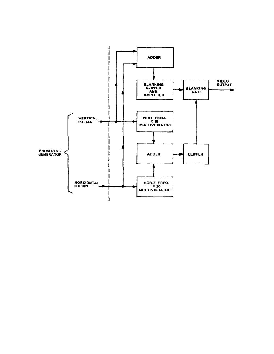
Figure 3-22.
Grating generator, block diagram
b. To prevent lines from appearing during retrace, the horizontal and
vertical retrace pulses are combined, as shown in Figure 3-22.
When added, they
form a blanking pulse, and this pulse is applied to the blanking gate circuit. An
output signal is produced only when the incoming signal is strong enough to
override the level of the blanking pulse.
c. The grating pattern is comprised of 14 horizontal bars and 17 vertical
bars.
The bars, being evenly spaced, conform with both the aspect ratio of the
television system and linearity chart, discussed later on.
d. The
grating generator also produces either horizontal or vertical bars
separately.
By selecting the output from either the times -15 or times -20
and applying it to the signal clipper, the generator output results
in horizontal
or vertical bars only.
71


 Previous Page
