5.
Normally the Y-RF signal at pin 1 of IC-2 (CX-130) is 0.7 Vp. If this signal level drops to 0.05
Vpp or below, a dropout is considered to have occurred. A dropout is a momentary loss of playback
signal that may be caused by discontinuities in tape-to-head contact or by a small imperfection in the
tape coating. When a dropout is detected, the dropout detector actuates the electronic switch (all inside
IC-1) and the switch replaces the portion of the signal during which the dropout occurs with Y-RF signal
from the previous line.
Learning Event 3:
FUNDAMENTALS OF THE COSINE EQUALIZER (HF-3 BOARD)
1.
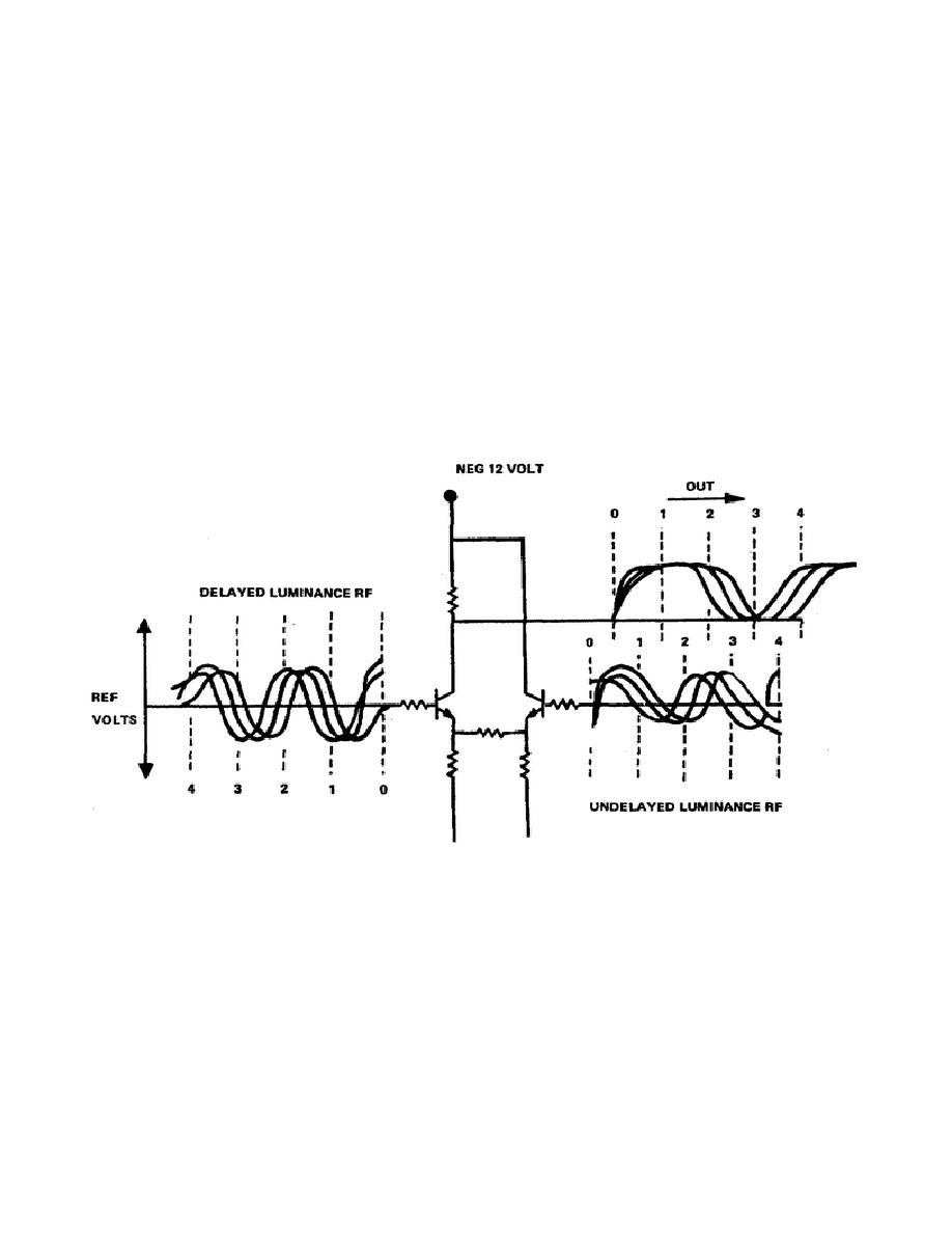
Refer to Figure 3-4 (fo) at end of lessons. The output of Y-RF OUT BUFFER Q7 (PS-10 Board)
is applied to a cosine equalizer circuit on the HF-3 board (fig 4-1). The incoming Y-RF signal is
buffered by transistor Q1 and follows two paths, one to the base of Q2 with a delay of 60 nanoseconds
and the other undelayed path to the base of Q3. Q2 and Q3 form a differential amplifier that compares
the delayed luminance RF with the undelayed fundamental.
Figure 4-1. Cosine equalizer
2.
The delay line has full-wave resonance at 4.1 MHz so that the output will vary around this center
frequency from sync tip at 3.58 MHz to peak white at 5.4 MHz. The differential output will be the
addition of the two sides. At 4.1 MHz, the two sides will be equal and the differential amplifier will
have a minimum output. AT 8.3 MHz, the output will be minimum since the delayed input will equal
the undelayed input. This will also be true at the lower 2 MHz frequency. At the middle frequencies
from 2 MHz to 4.1 MHz and from 4.1
25


 Previous Page
