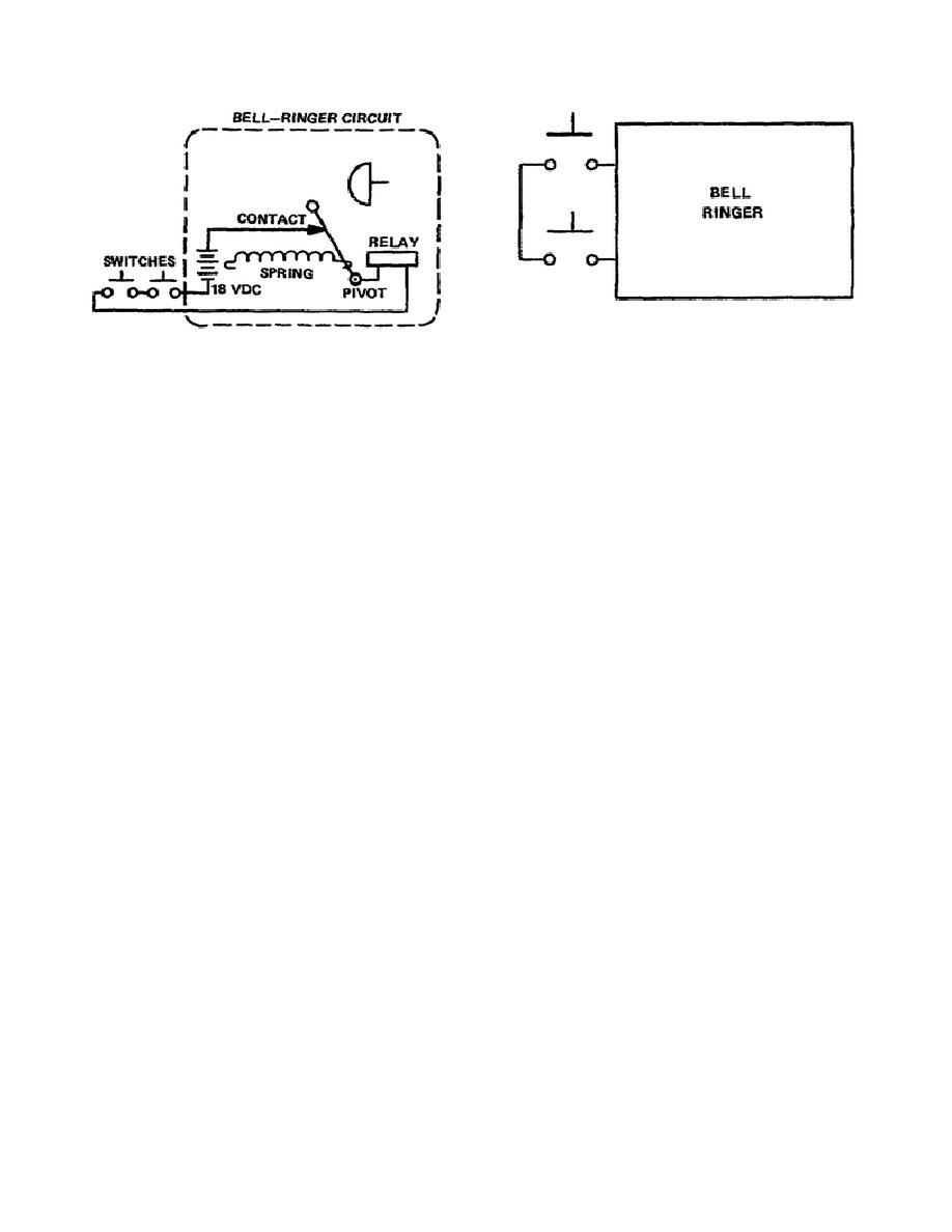
Figure 1-2. A symbol to replace
Figure 1-1. A schematic diagram
the schematic
b. Imagine expanding this idea to many different circuits, each represented by a symbol. It
means less time to trace through a large diagram, more consolidated prints (less room required for each
circuit,) and a lot less confusion of lines (wires) on the diagram. A logic diagram is just a print with
each circuit represented by a symbol instead of a schematic. The symbols are connected together by
lines to show how the output of one circuit connects to the input of another.
Learning Event 2:
DESCRIBE NEGATIVE AND POSITIVE LOGIC CIRCUITS
1.
Positive and negative logic circuits are basic circuits that are used to build positive and negative
logic systems. The terms "negative" and "positive" refer only to the relative voltage level of a signal.
These terms do not refer to the actual voltage level of either a binary 1 or a binary 0.
2.
For example, the two signal voltages in either a positive or a negative logic system may be either
negative or positive. Or one of the signals may be negative and the other positive. The important point
is that you should always be careful not to confuse the references to logic levels with the references to
voltage levels. It does not matter if a circuit uses negative or positive voltage.
3.
The term positive logic means that the circuit being referred to uses the more positive of two
signal voltages to represent binary 1.
a. For example, if the two signal voltages in a system happen to be 0 and +6 the more positive
of the two is +6. In this case then the +6-volt signal represents binary 1.
b. If the voltages are -6 and -12, the -6 is more positive. In this case the -6 represents binary 1.
2


 Previous Page
