19. Preinstallation checks. Set the LB/CB and MODE switch to the proper position. For our use, we
will install a telephone for point-to-point operation. Install the batteries in the telephone as discussed in
paragraph 16, then place the LB/CB switch in the LB position. The MODE switch is placed in the AC
SUPERVISION position. Now, if you pick up the handset, little or no sidetone can be heard in the
receiver when you speak into the microphone. When you press each key on the keysender pad, there is
little or no tone heard in the receiver. Switch the LB/CB switch to point-to-point. Speak into the
microphone and a tone should be heard. If you press each key on the keysender pad, you will hear a
tone that is lower than the previous one. Place the handset on the cradle. Using a flat-tip screwdriver,
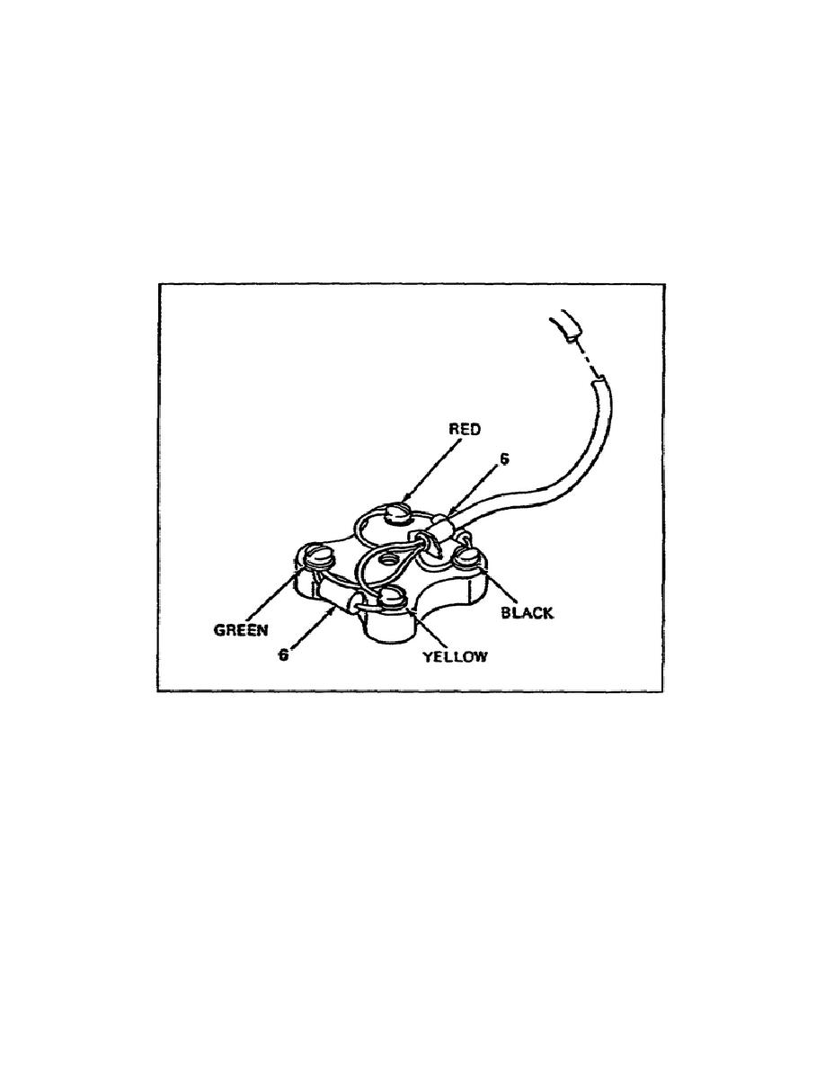
connect a resistor 1000 ohms between the red and black terminals on the connector block and another to
the green and yellow terminals (See Figure 1-4.)
Figure 1-4. Resistor connection.
20. Setting up for point-to-point operation. Remove the resistors from the connector block. It is now
time to connect the WF-16/U telephone cable to the terminal block. You must remove one inch of
insulation from each of the four wires to prepare them for connecting to the C42 block.
a. Connect the two brown wires to the R and Y terminals of the connector block. This is the
receive (RCV) side of the telephone set. Connect the two green wires to the G and B terminals of the
connector block. This is the transmit (XMIT) side.
SS0441
1-10


 Previous Page
