28.
Operator controls, indicators, and receptacles.
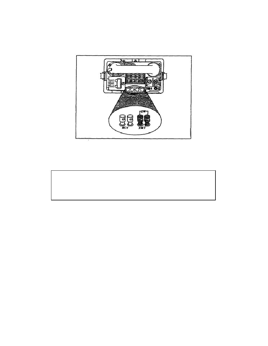
a. Binding posts. The two XMIT binding posts are color-coded black and marked with 2W.
The two RCV binding posts are color-coded red. (See Figure 1-8.)
Figure 1-8. Binding posts.
b. The wires connected to the binding posts must be clearly identified at all times. The wires
may be tagged, color-coded, or identified as directed by the team chief.
CAUTION
Do not attempt any wire connections if the wires are not clearly identified.
Ask your team chief for instructions if you have any questions.
c. For 4-wire operation, the pair of wires identified FROM RECEIVE are connected to the
XMIT binding post.
d. The pair of wires identified FROM SEND are connected to the RCV binding posts. (See
Figure 1-9.)
e. For 2-wire operation, the send/receive pair of wires are connected to the XMIT binding posts.
No wires are connected to the RCV binding posts. (See Figure 1-10.)
f. The LED RING indicator lamp is controlled by the ON-OFF switch and will glow when a
ringing signal is received. (See Figure 1-11.)
SS0441
1-16


 Previous Page
