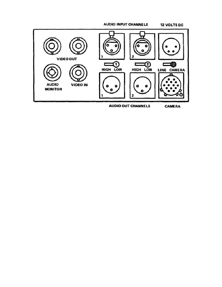
Figure 1-11.
VR input and outputs
a. For viewing video on a monitor, other than the viewfinder, or for
recording on an additional recorder, the VIDEO OUT-1 or VIDEO OUT-2 would be
connected to a video monitor or a second recorder.
b. To connect an additional signal source to the camera the operator
would use the VIDEO IN connector.
c. In the event the operator wanted to add several microphones using an
audio mixer, the operator would connect this to the AUDIO IN AUDIO-1 or
AUDIO-2 connectors. Because of the difference of impedance in microphones,
there is a LINE HIGH/LOW selector switch to correct this.
d. As with the two AUDIO IN connectors, there are
two
AUDIO
OUT
connectors for hearing audio from the two audio channels.
e. When operating the recorder with the camera, a cable is used and
connected to the CAMERA connector.
At this time a switch for MIC
LINE/CAMERA select switch is put into the camera position.
When using
external signals from VIDEO IN and AUDIO IN connector, the operator must put
the MIC LINE/CAMERA select switch into the line position.
f. In order to use AC outlets instead of battery power the operator can
connect an AC power adapter to the DC 12 volt input connector. While the AC
adapter is connected, the operator can charge any batteries connected (fig
1-11).
24


 Previous Page
