b. Voltmeter.
The meter movement discussed above can be used either as an
ammeter or a voltmeter. How is this possible?
You can measure voltage with the
ammeter just described by placing resistance in series (not parallel) with the
meter coil and measure the current flowing through the coil.
In other words, a
voltmeter is a current-measuring instrument designed to indicate voltage by
measuring the current through a resistance of known value.
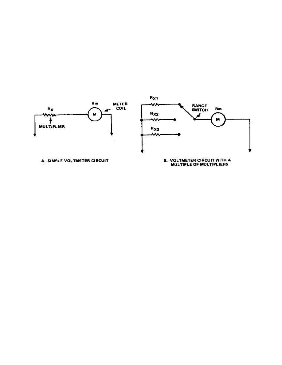
(1) A typical voltmeter circuit, shown in Figure 1-6a, is a simple-series
circuit. As with the ammeter, it is possible to obtain various voltage ranges with
a voltmeter.
To obtain more than one range, various sized resistors, called
"multipliers," are added in series with the coil, as shown in Figure 1-6b.
Figure 1-6.
Typical voltmeter circuit
(2) The accuracy of any measurement made with a voltmeter depends, for the
most part, upon the relationship between the total resistance in the meter circuit
and the value of resistance across which the voltage is measured. This fact can be
seen from a study of the circuit in Figure 1-7, showing both the actual voltage and
the measured voltage as well as percentage of error.
Observe that the voltage
measured is two-thirds the actual voltage across RM, an error of 33.3 percent,
since the meter resistance is only one-half the value of the total resistance in
the circuit.
6


 Previous Page
