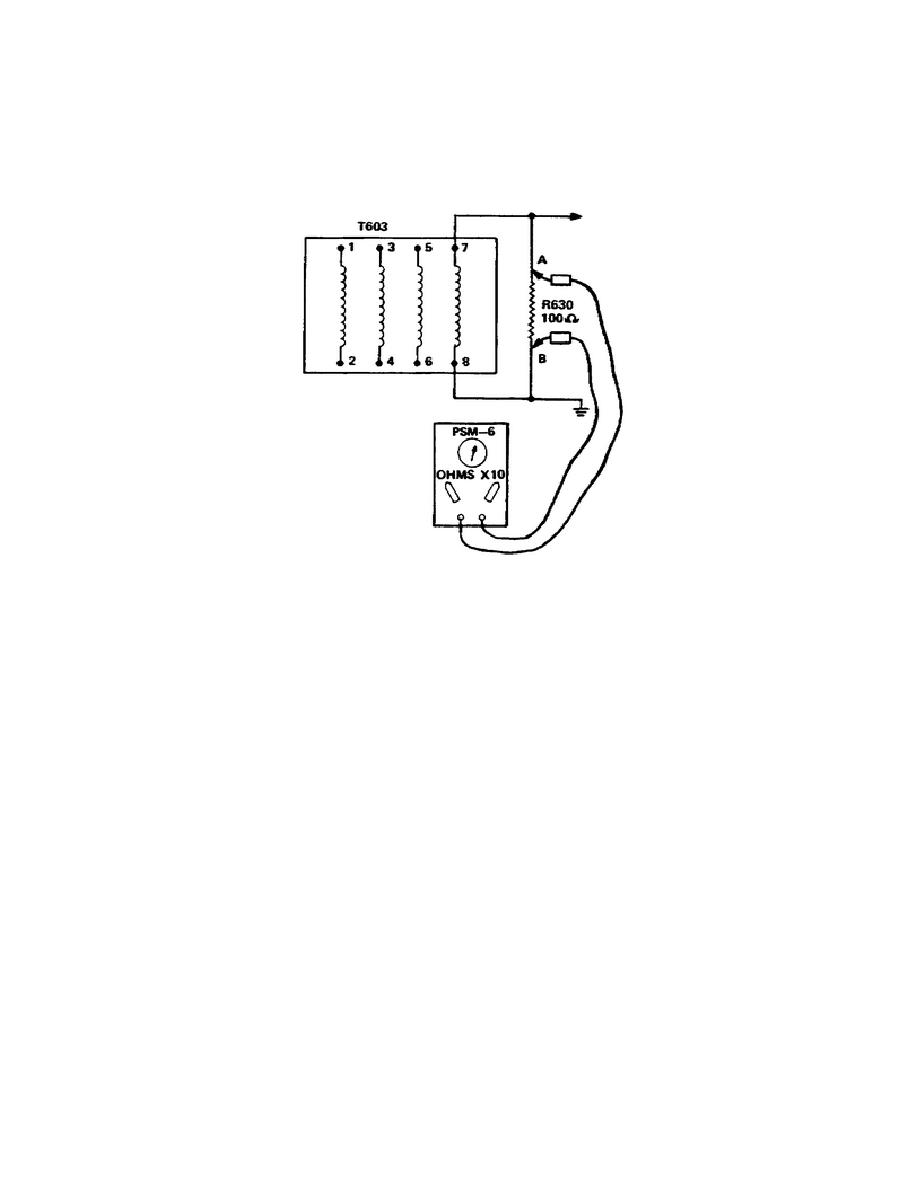
Therefore, the current from the meter is flowing through two parallel paths, and
the resistance measured by the meter is the less than total resistance of R630. To
prevent this situation you must disconnect one end of R630 and then measure its
resistance.
In this way you can measure the true value of R630.
Remember that
when you measure a specific resistance, you should eliminate any parallel paths in
order for the reading to be accurate.
Figure 1-24.
Resistance measurement proper circuit conditions
3.
Another point you should remember when measuring resistance with an ohmmeter
is illustrated in Figure 1-25, which shows a portion of a typical voltage regulator
circuit. Suppose that you want to measure the resistance of potentiometer R1. Of
course the circuit power is turned off, and parallel paths have been eliminated by
disconnecting leads X and Y. Now all you have to do is measure the resistance of
RI. However, in this case the terminals of R1 are hard to reach; so you place your
fingers on the metal tips of the meter leads in order to hold the leads on the
potentiometer terminals.
The meter has only about a 1.34-volt or 13.4-volt
battery, so you will not get a shock. You have overlooked one little detail. You
have placed yourself in parallel with R1.
You will probably obtain a resistance
reading of 150,000 to 200,000 ohms, which is the sum of a parallel circuit made up
of you and R1. Although there is no safety factor involved in this example, you
have obtained an erroneous meter reading which would probably lead you down the
wrong trail when troubleshooting a circuit of this type. This in turn wastes time
and can cause unnecessary replacement of components or parts.
27


 Previous Page
