e. By injecting the grating pattern into a receiver or monitor and checking
the display uniformity, you can determine discrepancies in the deflection circuit's
linearity. The linearity is adjusted properly if the vertical and horizontal bars
are both uniformly spaced over the entire viewing area.
The grating pattern is
also useful when you adjust the linearity of a camera chain.
f. Another valuable feature of the grating pattern is apparent when you
adjust the convergence of a color receiver or monitor.
3.
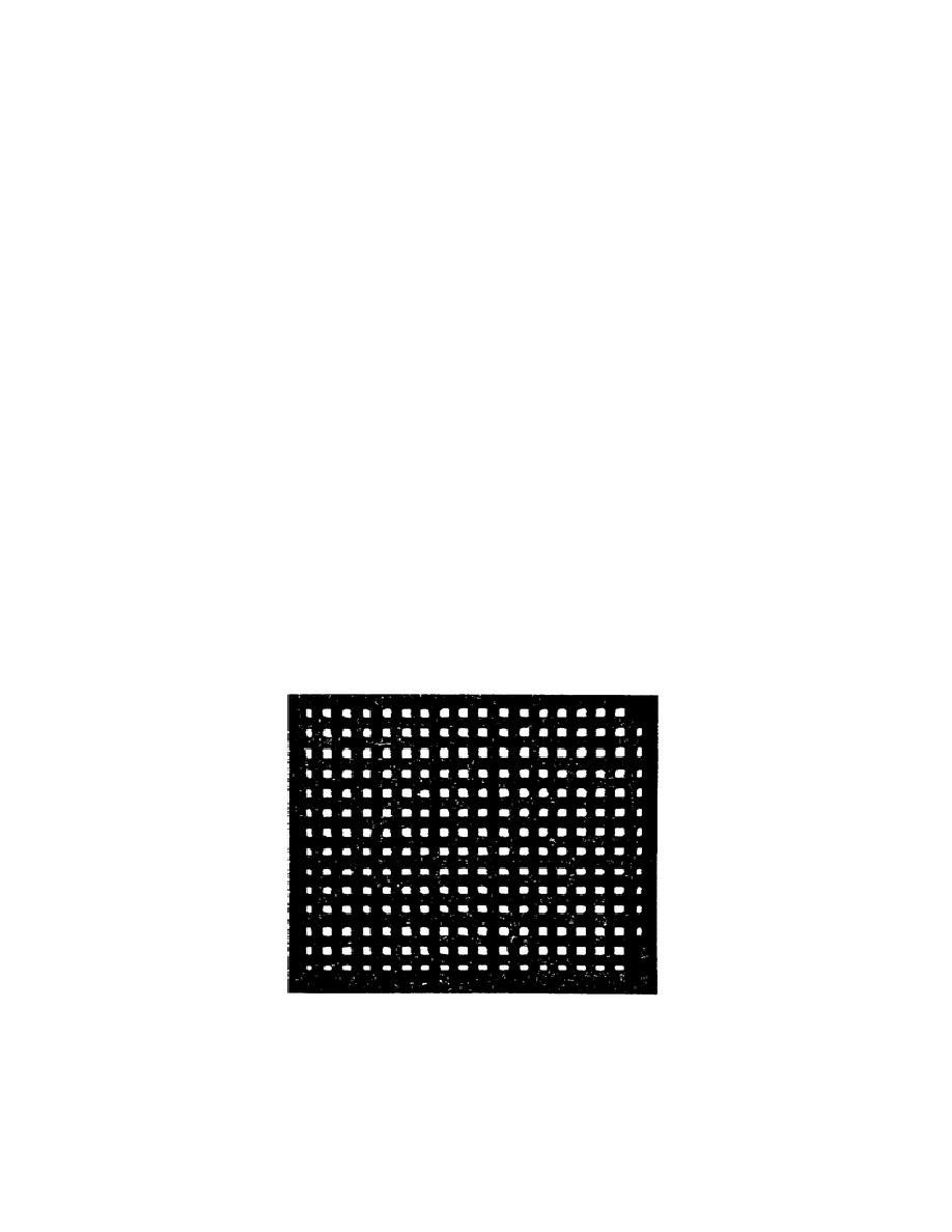
The same generator is often used to generate the dot pattern or the grating
pattern. Only the clipper bias point will determine which output is produced. If
the signal clipper bias is so adjusted for an output only when horizontal and
vertical pulses are added, a dot pattern results (fig 3-23). The other circuits in
the dot bar generator and their operation are identical to those in the grating
generator.
4.
The video sweep marker generator is a convenient device for checking the
frequency response of a given amplifier.
a. In a typical generator, the output of a fixed RF oscillator, operating at
approximately 70 MHz, is heterodyned against a sweep frequency oscillator.
The
sweep oscillator is being swept at a 60-Hz rate. The 0- to 10-MHz beat frequency
is then applied to the circuit or unit being tested, and the resulting output,
after detection, is observed on a scope.
b. Marker notches are inserted at 1-MHZ intervals for frequency calibration
of the beat frequency; this is accomplished by an additional oscillator stage in
the sweep generator.
c. A more accurate means of calibrating can be obtained with a sweep
generator unit that uses a calibrated CW oscillator as a marker source. This type
of marker source provides either variable or fixed markers over a marker source
range of 100 kHz or 10 MHz.
Figure 3-23.
Dot test pattern
72


 Previous Page
