3.
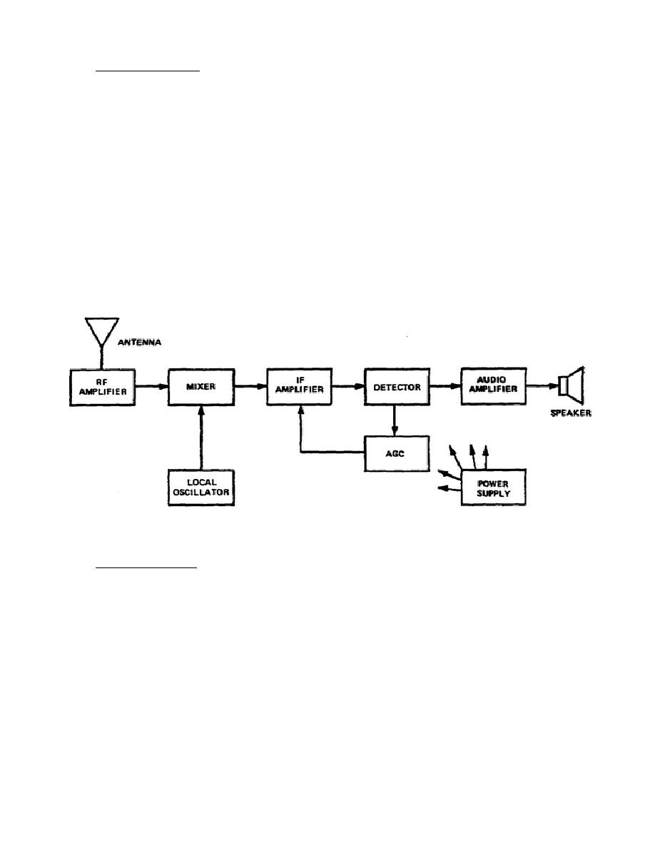
Heterodyne Process. Figure 4-2 is a block diagram of a superheterodyne radio-receiver. This
receiver produces a carrier at a new frequency, keeping the information being transmitted unchanged.
a. To help you understand how the superheterodyne radio works, look at the section of the radio
in which all of the tuning and station selection occurs (consists of the RF amplifier, the mixer, and the
local oscillator). This section of the receiver receives the signal being broadcasted, heterodyne this
signal with the one that is produced in the local oscillator and a third signal is produced called the
Intermediate Frequency (IF) signal. This IF signal is processed through the radio and soon the original
broadcasted information is heard coming out of the speaker.
b. Figure 4-2 illustrates two carrier signals being mixed in the superheterodyne system
(receiver). F1 and F2 will be heterodyned in the mixer block of the receiver, and the result is the
production of four signals. They are: F1 at 1.5 N1Hz, F2 at 1MRz, the sum of the two signals (F1+ F2) or
2.5MHz, and the difference of the two signals (F1 - F2) or 0.5MHz. If, however, the incoming signal at
F2 was modulated, then both the sum and the difference signal would contain modulation.
Figure 4-2. The heterodyning process produces four signals through the action of the mixer stage
4.
AM's disadvantage. AM's biggest disadvantage, to be discussed further in the next learning
event, is that electrical discharges in the air allows the carrier to be amplitude-modulated. As a result the
listener hears interference and static and very often noise will override the modulation and interrupt the
broadcast signal rather than the amplitude. The limiter block in the receiver cuts off any and all
amplitude modulation intelligence upon receiving a frequency modulation signal.
37


 Previous Page
