SS0607-8
30 September 1988
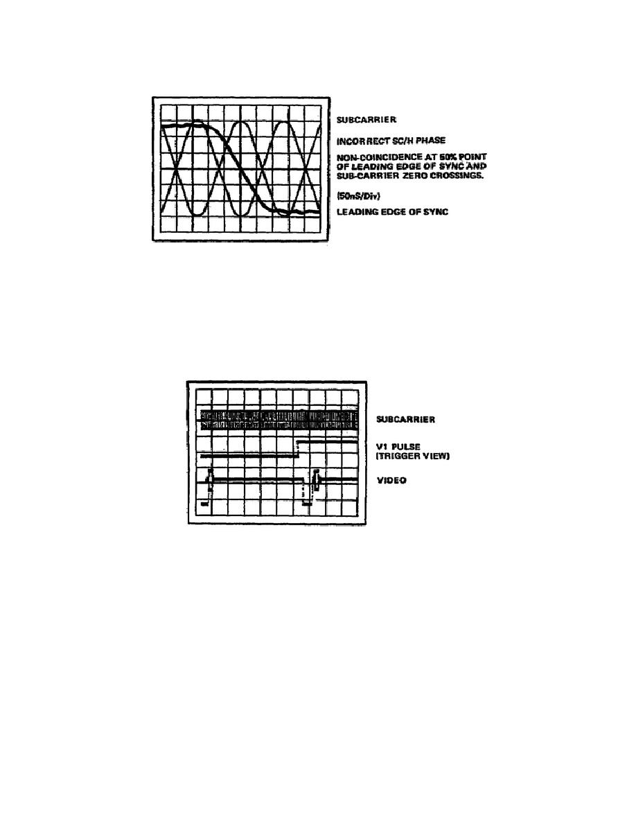
Figure 3-9.
Improperly-phased SC/H signal (70-phase error)
i. Adjust the SC/H phase as described in steps 5a through 5h for proper
coincidence.
j. Trigger the oscilloscope on the leading edge of the V1 pulse with
video and subcarrier connected to the two input channels (fig 3-10).
Figure 3-10.
Subcarrier, V1 pulse, and video display
k. Increase the oscilloscope sweep rate and use the delayed sweep
option to view a display showing the first leading edge of sync following
the trigger.
l. If the negative transition of the subcarrier is coincident with the
leading edge of sync, the triggering V1 pulse is a color frame
identification pulse that occurs on line 11 of field 1 (fig 3-11).
NOTE: The SC/H phase is
easiest to observe on a display that is
horizontally triggered.
Because of the low repetition rate of V1
and the fast sweep rates
(50 ns/div) required, only the direction
of subcarrier signal can
be easily observed by triggering on V1.
32


 Previous Page
