b. Signal monitoring.
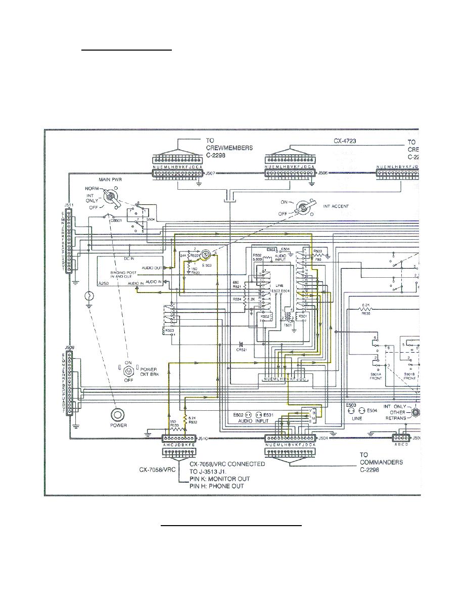
(1) The audio signal from the J-3514/U J1 pin H (PHONE OUT) is applied
through the CX-7058/VRC to the AM-1780 J510 pin H. Within the AM-1780 the
audio signal is applied to J504, J505, J506, and J507 pins B.
Then the
audio signal is applied through each CX-4723 pin B to the respective C-2298.
When the MONITOR switch of the C-2298 is set to B, only the R-442 received
signal can be monitored (Figure 96. Issued as adjunctive material.).
(continued on next page)
Figure 96.
Monitor circuit.
109


 Previous Page
