1. Assigned frequencies. It is necessary to assign hypothetical frequencies of operation in the uplinks and
downlinks given in Figure 1-10 to show the functions of the block diagrams. We will assume frequency
assignments as follows:
a. Communications (FM).
Terminal A to B uplink:
7,360 MHz (f1a)
Terminal A to B downlink:
1,815 MHz (f1b)
Terminal B to A uplink:
7,260 MHz (f2a)
Terminal B to A downlink:
1,715 MHz (f2b)
b. Beacon (FM). The bacon signal (f5) is downlink only at 1,820 MHz.
c. Command (AM). The command signal (f4) is uplink only at 148 MHz.
d. Telemetry (FM). The telemetry signal (f3) is downlink only centering on 136 MHz.
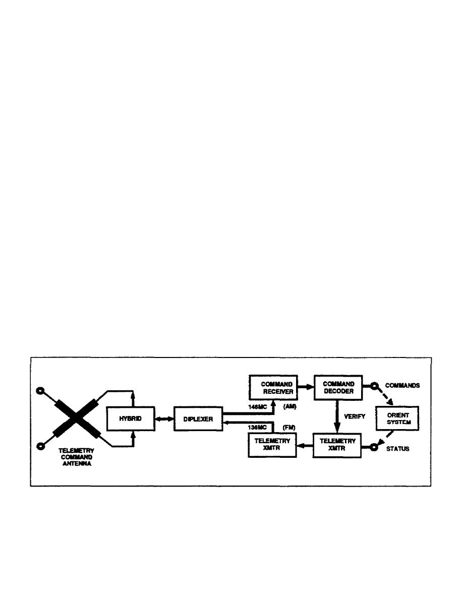
2. Command. The block diagram of the command and telemetry sections is shown in Figure 1-10. The
turnstile antenna, consisting of the four elements projecting from the bottom of the satellite, is used to receive
ground-station commands and to transmit telemetry. The hybrid network, together with the diplexer, minimizes
interaction between the command (f4) and telemetry (f3) signals. Reduction of interaction is further assured by
using AM for command and FM for telemetry. The command receiver demodulates the command signal to
extract its sequentially coded intelligence. The command decoder then furnishes the respective commands to
the appropriate subservient circuits. One command channel verifies to the telemetry channel that the command
signal has been received in the satellite. Commands transmitted to the satellite include signals for telemetry and
communications system switching, gas jet firing, and apogee motor firing.
Figure 1-10. Command and telemetry section of synchronous communications satellite, block diagram.
1-35
SS0031


 Previous Page
