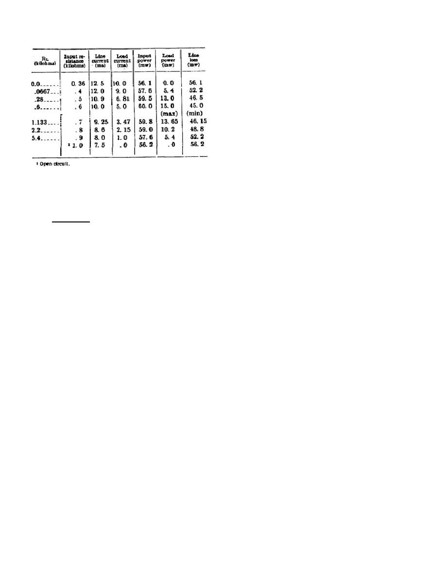
(4) The power delivered to a load resistance varied on either side of 600 ohms in such a circuit is tabulated in
Table #3 at left of page. The tabulation shows that maximum power is transferred to the load by the transmission
line when the line is terminated in its
characteristic resistance (600 ohms, in this
example). Note that, although the input power
varies only slightly when the termination is not
ZO, the load power varies considerably from its
maximum value.
TABLE #3.
In order to reduce the line loss to a minimum, therefore, the line must be terminated in its characteristic impedance.
61.
Attenuation.
Attenuation is the term used to express the loss of power that occurs in a network or transmission line. This
loss is attributable to the line parameters, especially the series resistance and shunt conductance. These constants, whether
distributed or lumped, dissipate power in the line and therefore cause the output power of the line to be less than its input
power. This is illustrated in figure 59, and in the table (par. 60b(4)). For example, in C, the power delivered to the line is
60 mw, whereas the load power is only 15 mw. The difference in power, 45 mw, is dissipated in the three resistances of
the tee section. By noting the currents in these resistances, it will be seen that the left-hand 200-ohm resistance dissipates
(10)2 times .2, or 20 mw; the right-hand 200-ohm resistance dissipates (5)2 times .2, or 5 mw; and the shunt 800-ohm
resistance dissipates (5)2 times .8, or 20 mw. Thus, the total dissipation is 45 mw.
a. Decibel. Ordinarily, the attenuation of a line is expressed as a ratio of input to output power. To simplify
such calculations, the dB (decibel) has been adopted as a measure of attenuation. A decibel is defined as the attenuation
which occurs on a line when the ratio of input to output power is 1.25. The total attenuation in decibels of a transmission
line can be calculated by using the following formula:
128


 Previous Page
