LEARNING EVENT 15: MODULATOR STAGES
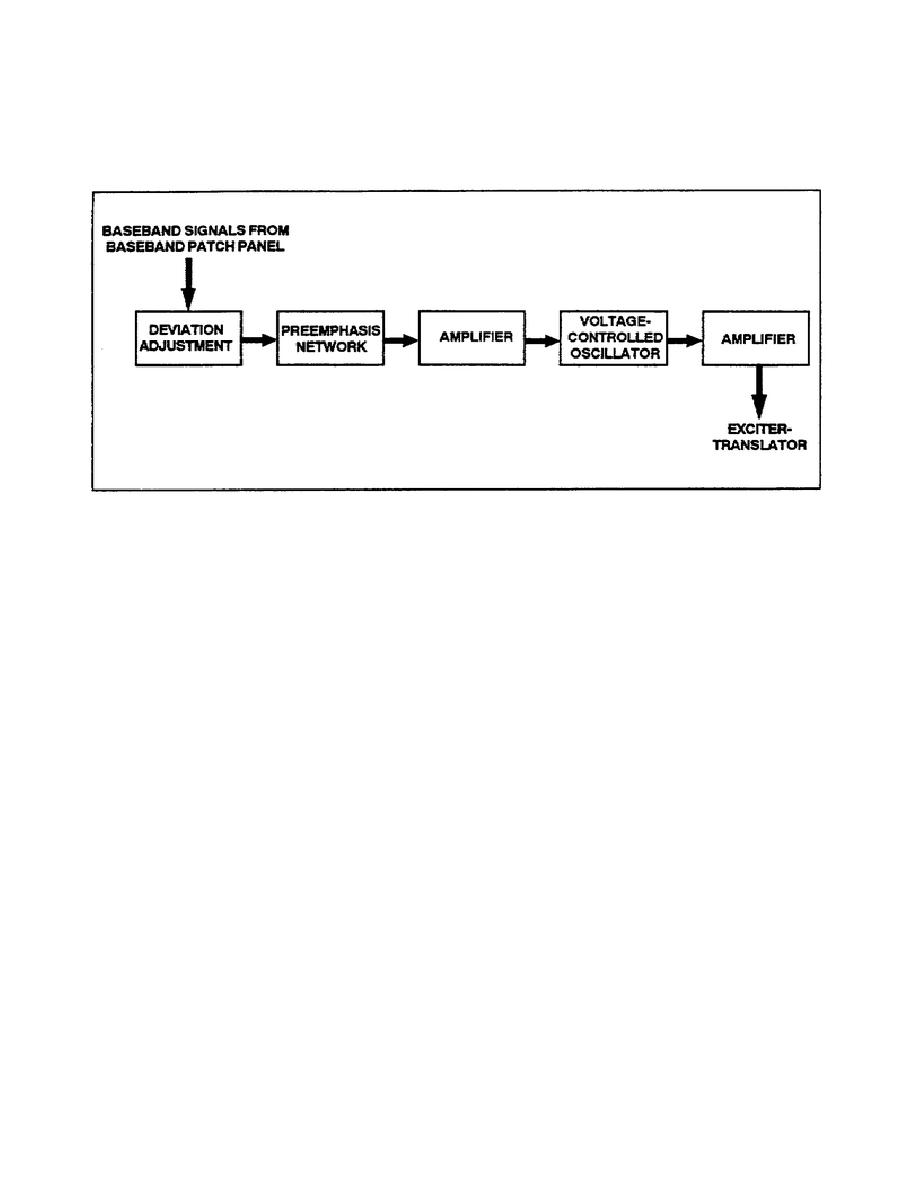
1. A typical modulator unit will contain various shaping circuits and amplifiers, as well as the actual
modulating circuit. A block diagram of a simplified modulator unit is represented in Figure 2-13.
Figure 2-13. Simplified modulator unit.
2. The normal baseband input is coupled from the baseband patch panel to a series of circuits which prepare
the baseband signals for modulation.
a. Deviation adjustment are used to establish the desired amplitude of the baseband signals and, since
signal amplitudes are converted to frequency deviations during modulation, the adjustments also determine the
frequency deviations of the modulated signals.
b. A preemphasis network emphasizes the high-frequency components by reducing the amplitude of the
low-frequency components of the baseband signal by a greater amount than that of the higher frequencies. This
unbalance in the overall sign causes the signal power level in the receiver (after demodulation and filtering) to
be increasingly large at the higher frequencies, thus compensating for the increased noise that occurs at the
higher frequencies. The receiver will be equipped with a deemphasis circuit to restore the signal to its original
amplitude. This compensation tends to equalize the S/N across the frequency band. A preemphasis network is
also called a high-pass filter circuit.
c. The baseband amplifier provides the required amplification for the baseband signals prior to modulation.
In some modulators, the amplifier network comprises additional shaping circuits, such as clippers, limiters,
preemphasis networks, deemphasis networks, and filters. These additional shaping circuits are used to reduce
the overall noise and to improve the baseband signal.
3. Direct- and indirect-angle-modulation techniques are employed in various types of microwave
communications terminals.
2-13
SS0031


 Previous Page
