3. Strange as it may seem, the gain of the waveguide radiator is somewhat greater than the gain of a dipole.
The polar distribution in the electric plane is similar to the figure 8 pattern of the dipole. The waveguide
radiator also has a greater tuning range than the dipole. The tuning range limits are the same as the waveguide
limits. As the frequency of the energy in the waveguide is increased to where the waveguide dimension is more
than one wavelength, the energy is attenuated. Also, if the frequency is decreased sufficiently, it will reach the
cutoff frequency of the waveguide, and propagation ceases.
LEARNING EVENT 8: DIPOLE TERMINATION
The fact that a waveguide radiator has greater gain than a dipole might lead you to think it is a simple way to
radiate energy into space. Actually it is simple, but there is still the problem of the impedance mismatch
between the waveguide and space. An impedance mismatch prevents maximum transfer of energy, so energy is
lost in the waveguide because of standing waves.
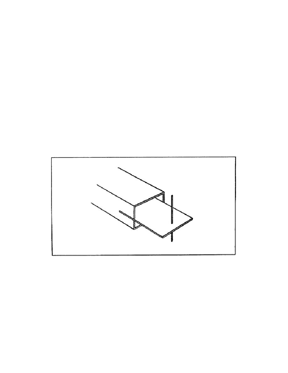
1. If a waveguide is terminated with a dipole, as shown in Figure 2-7, a good impedance match can be
obtained. It is much simpler to excite a dipole from a waveguide than from a coaxial line. To excite a dipole
from a waveguide, the dipole is mounted on a web that fits into the open end of the waveguide. The web is
mounted in the waveguide so that it is parallel with the wide side of the waveguide. This places the dipole so
that it is parallel to the E lines in the waveguide.
Figure 2-7. Dipole termination of a waveguide.
2. The impedance of the dipole is determined by the depth to which the web is inserted and the position of the
dipole with respect to the opening in the waveguide. Usually, the waveguide has a tapered section on the end
and the web is inserted in this section. This provides a very good impedance match between the waveguide and
space.
SS0031
2-8


 Previous Page
