53.
Common-Battery Antisidetone Circuit.
a. Arrangement. As already explained, a high level of sidetone is undesirable in telephone receivers. It
produces interference when the set is operated in noisy locations, and usually makes the user lower his voice when he
hears his spoken words reproduced loudly by his own receiver, thus reducing the output of his transmitter to the line.
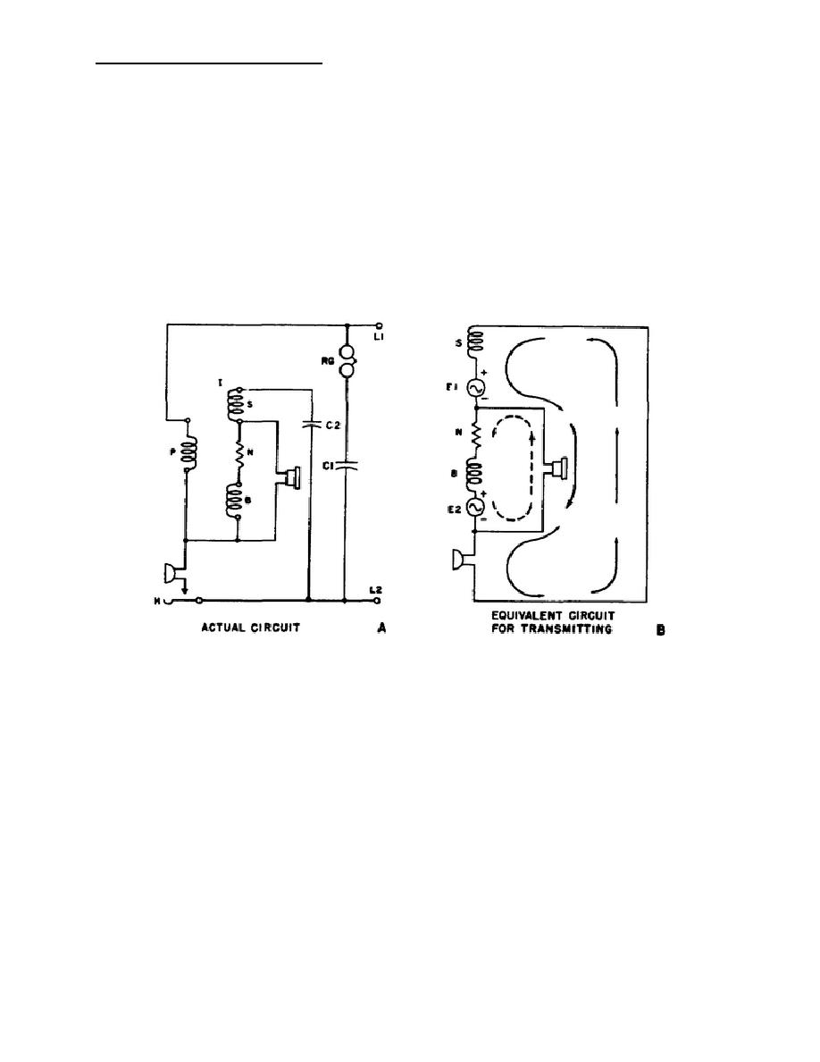
Both of the common-battery sets discussed in paragraphs 51 and 52 produce sidetone. An antisidetone circuit which
reduces sidetone to a very low level is illustrated in figure 48. The actual circuit diagram, in A, shows a three-winding
induction coil. The primary circuit consists of a single primary winding, P, in series with the transmitter. The secondary
circuit consists of two secondary windings, S and B, with a resistor, N, connected between them. The receiver is
connected across the series combination of the resistor and secondary winding B, as shown.
FIGURE 48. Common-battery Anti-Sidetone Circuit.
102


 Previous Page
