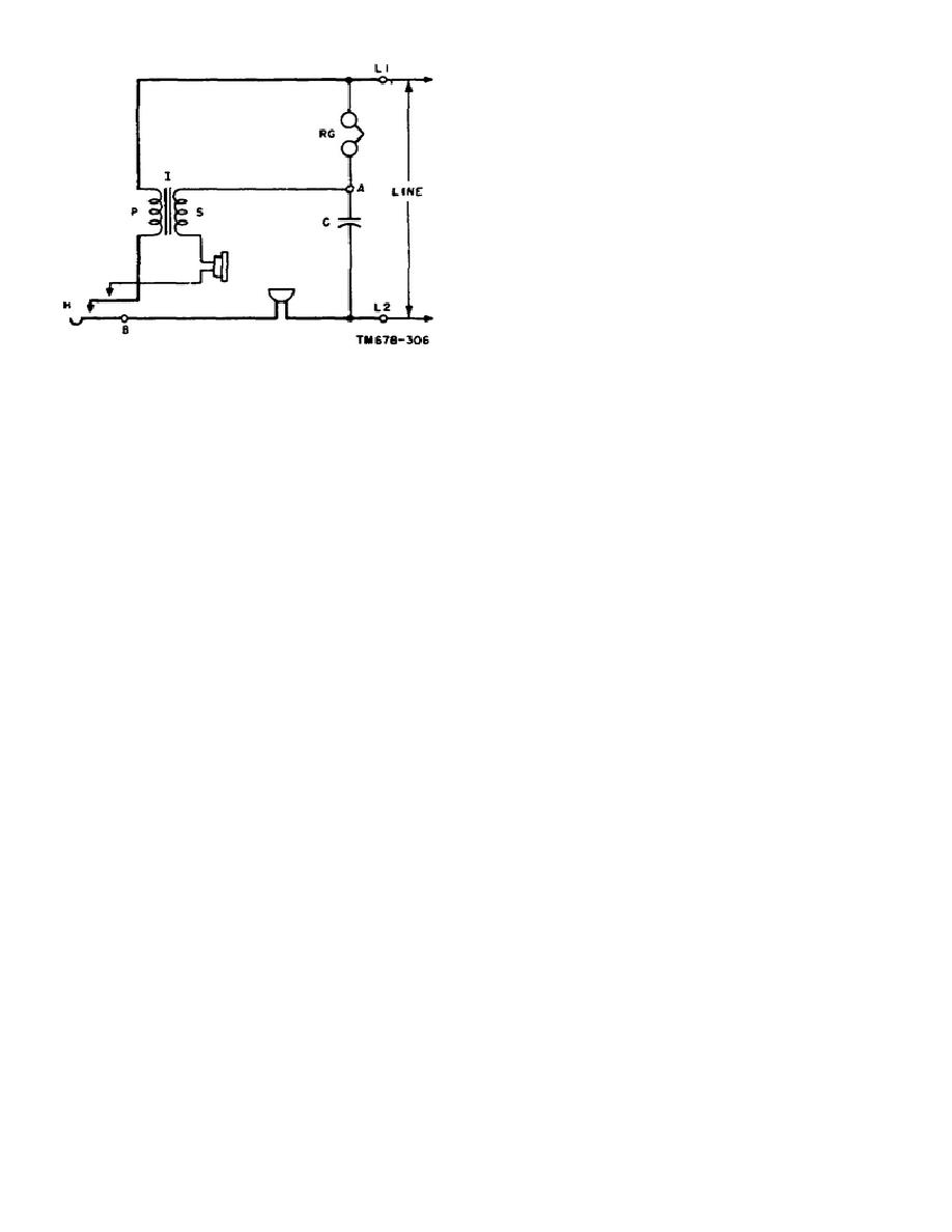
b. Transmitting circuit. When hookswitch H is
closed, dc voltage from the central office battery is applied
to the components of the telephone set shown in figure 46.
Application of this dc voltage produces a dc current flow
in two paths. One current path (path 1) is through the
primary of induction coil I, hookswitch H, and the
transmitter. The other dc path (path 2) is through ringer
RG, the secondary winding of the induction coil, the
receiver, the hookswitch, and the transmitter. The amount
of direct current flowing through path 2 is less than that
through path 1 because of the higher ohmic resistance of
path 2.
FIGURE 46. Arrangement of Common-
Battery Sidetone Circuit.
(1) When a voice-frequency sound activates the diaphragm of the transmitter and disturbs the position of the
carbon granules in the transmitter, the current in the two paths varies in accordance with the frequency and amplitude of
the sound wave. As a result, a voice-frequency component of current is developed through path 1 and the line, with
voice-frequency voltages appearing across the transmitter and the primary winding of the coil. Little voice current flows
through path 2, because the voice current through this path is limited by the high impedance of the ringer as compared to
the impedances of the receiver and secondary winding. However, voice current in the primary winding through path 1
induces, by transformer action, a voice current in the path comprised of the secondary winding, the receiver, the
hookswitch, the transmitter, and the capacitor.
(2) The connections to the primary windings of the induction coil are made so that the primary and secondary
currents are in phase with each other. As a result, the primary and secondary currents combine in the common impedance
presented by the transmitter, and the resultant voice current sent out over the line is boosted to a higher level. Also, the
increased secondary current produces a larger local receiver current, and a high level of sidetone is obtained.
99


 Previous Page
