(1) Equalizer used.
The standard equalizer used on military
telephone circuits is Envelope Delay and Amplitude Equalizer CN-1234A/GCC,
shown in figure 9 of appendix A, section V. The function of this equalizer
is to provide the inverse characteristics of an unequalized telephone
circuit. In so doing it compensates for amplitude-frequency distortion and
envelope-delay distortion.
It contains 12 equalizer sections arranged in
series (cascade).
Delays are therefore additive, and the single-stage
amplifier gains are multiplied. Each section has a FREQUENCY KHZ switch, a
DELAY control, and an AMPLITUDE control.
The FREQUENCY KHZ switch may be
set to any one of ten discrete frequencies for delay insertion. Delay will
be longest, and amplitude will be greatest at the frequency selected by a
given equalizer section. Thus, the DELAY and AMPLITUDE controls have their
greatest effect at the frequency selected by the FREQUENCY KHZ control.
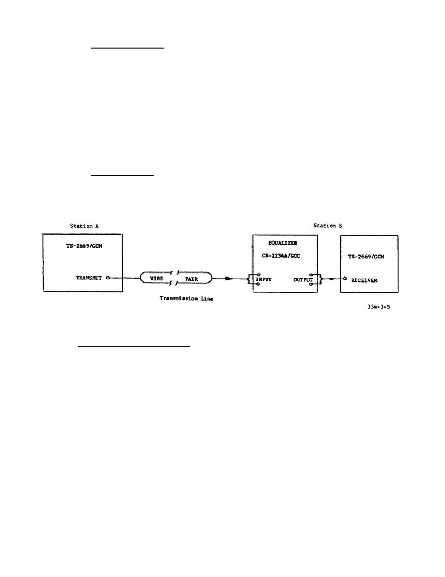
(2) Block diagram. The equalizer is connected into the circuit along
with the distortion measuring test sets as shown in figure 2-5. Either the
TS-2669/GCM or the 340B can be used for this test.
The technician can
choose the test method, either end-to-end, or end-to-end with reference
return.
Figure 2-5.
Line equalization, block diagram.
Recording of test data is not a formal
matter at this point because we are not interested in determining
characteristics of the line.
We are interested in correcting these
characteristics to modify them to parameter requirements. From the previous
tests we know the maximum and minimum values of envelope delay and of loss.
Our purpose in performing the equalizing procedure is to minimize these
effects across the spectrum of interest. However, to perform the procedure
efficiently, the technician should plot an amplitude-frequency response
curve, as
62


 Previous Page
