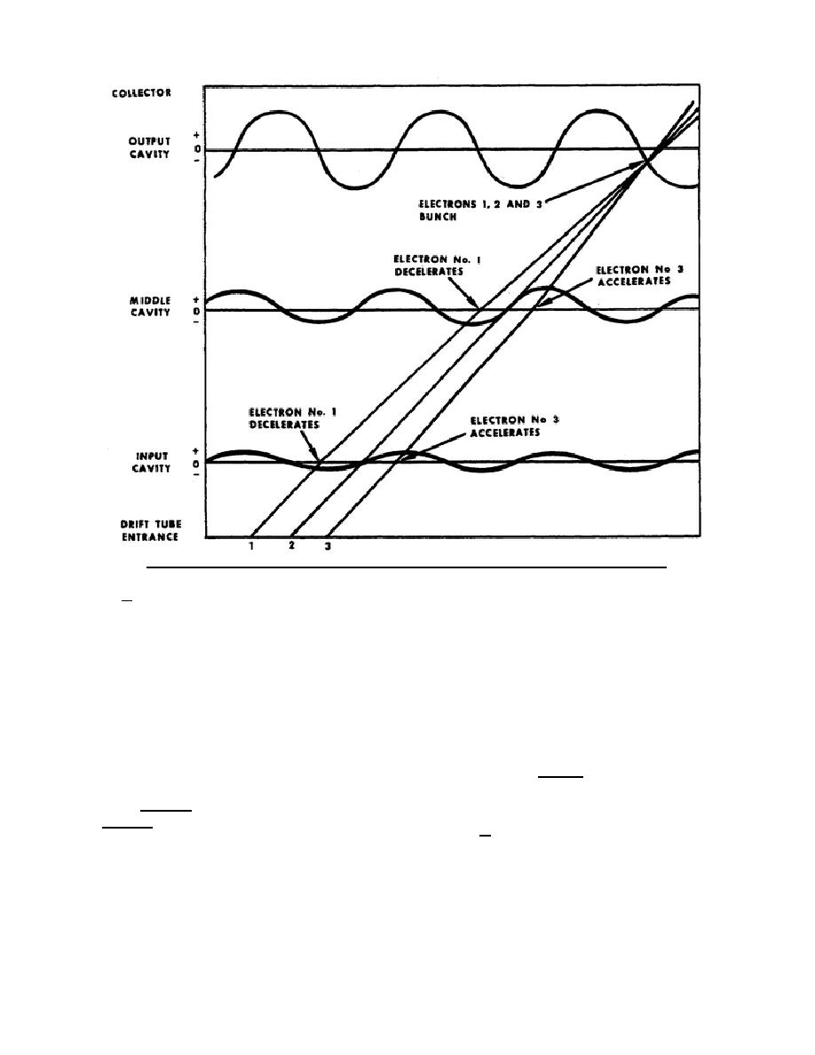
Figure 49. Applegate diagram showing beam electrons velocity and density modulation.
c. Now refer to figure 49 and notice that
(2) A short time after electron number
the diagonal lines are numbered 1, 2, and 3. For the
1, electron number 2 passes the first gap, and then
purpose of this explanation let's assume that these
the second gap. However, electron number 2 passes
lines are electron paths. As shown, all three lines
each gap at a time when the cavity RF voltage is
have equal slopes (parallel to each other) until they
zero.
reach the input cavity waveform. This indicates that
(3) Exactly one-half cycle after electron
all three electrons have equal velocities until they
number 1, electron number 3 passes the first and
reach the first gap, as follows.
second gaps. Notice that at this time both cavity RF
(1) Electron number 1 passes the first
voltages are positive. Electron number 3, therefore,
gap when the input cavity RF voltage is negative,
accelerates at each gap crossing. This acceleration is
electron number 1 surrenders a portion of its energy
indicated by the upward bends in line number 3
to the input cavity. This causes the velocity of the
where it crosses the input and middle cavity
electron to decrease. This deceleration is indicated
waveforms.
by a decrease in the slope of line 1 where it crosses
d. Although each electron enters the
the input cavity waveform. Electron number 1
drift tube at a different time, all three
continues through the middle cavity at a time when
electrons reach the output cavity at the same
the RF voltage is negative. This negative voltage
causes electron number 1 to lose additional energy
and further deceleration.
344 L1
47


 Previous Page
