are beyond the scope of this text.
Detailed
is larger when you are operating at saturation than
procedures are provided in instruction manuals for
below saturation.
individual tube type. The steps below are merely an
indication of the equipment which is necessary and
Section V. GENERAL REQUIREMENTS FOR
the general procedures to be followed.
KLYSTRON APPLICATION
a. The first consideration is the RF driver
1-58.
PROTECTIVE DEVICES
whose frequency can be electronically swept rapidly,
and whose power output is constant as it is swept in
a. Systems in which the klystron is used
frequency.
In addition, you'll need a crystal
usually provide built-in protective devices for the
detector, a sweep signal generation and an
tube.
It is important that you become fully
oscilloscope.
acquainted with them.
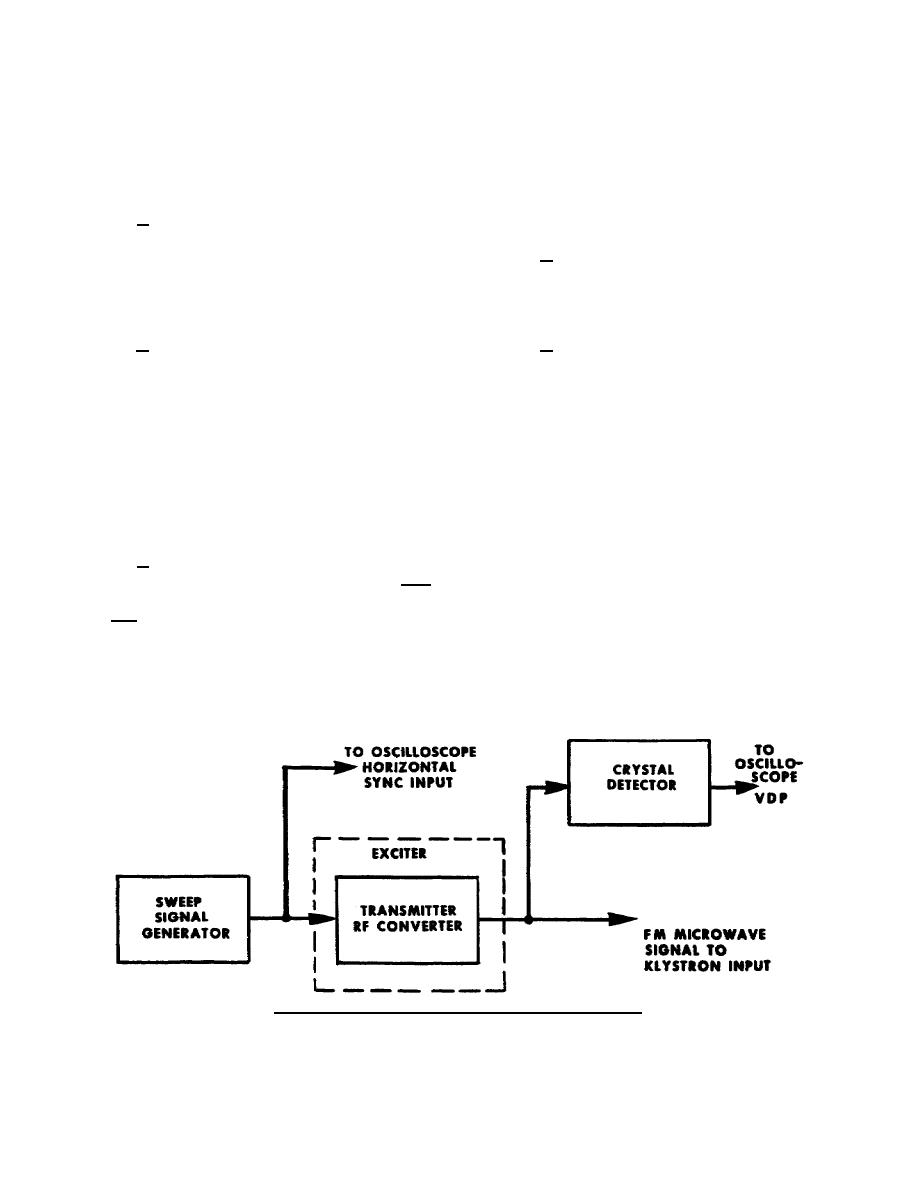
b. The diagram in figure 59 shows the
b. Some protective devices and their
method of connecting the test equipment to the
function are listed below. These are installed on
exciter. You will need to sample the exciter's RF
equipment to prevent damage to the klystron in the
output with the crystal detector. Therefore, you
event of equipment malfunction.
apply the detector's output to the Y-axis of the
oscilloscope so that you can see the pass band of the
(1) Air flow and water flow interlocks
tube. The X-axis of the oscilloscope sweep must be
to remove all electro potentials in case of cooling
synchronized with the RF input sweep voltage. So
failure.
you have to apply the exciter's RF input sweep
voltage (from sweep signal generator) to the
(2) Body current overload relay to
horizontal sync input of the oscilloscope.
remove beam power when maximum body current is
exceeded.
c. To broad band the tube, it is usually best
to detune the penultimate cavity to the high
(3) Current overload relays to remove
frequency side, and to detune the second cavity to
the beam power and cathode heating power in the
the low frequency side (assuming a four-cavity
event that excessive current should flow in either of
klystron here). The input and output cavity normally
those circuits.
are left tuned to the center of the passband. It may
be desirable to adjust the RF input power
(4) VSWR interlock to remove the
periodically, as you detune the klystron, to keep
beam power of RF drive in the case of malfunction
operating near saturation. The bandwidth of the tube
of the transmission line or antenna.
Figure 59. Broad-banding with sweep signal generator.
344 L1
55


 Previous Page
