caused by the limits of the conductivity of the transmission line, and establishes conditions that make possible the
propagation of nonradiating waves. If the phase velocity can be reduced enough, for instance, by covering the
surface of the wire with a dielectric layer, the nonradiating wave becomes stable and can be excited more easily
and with a high degree of efficiency.
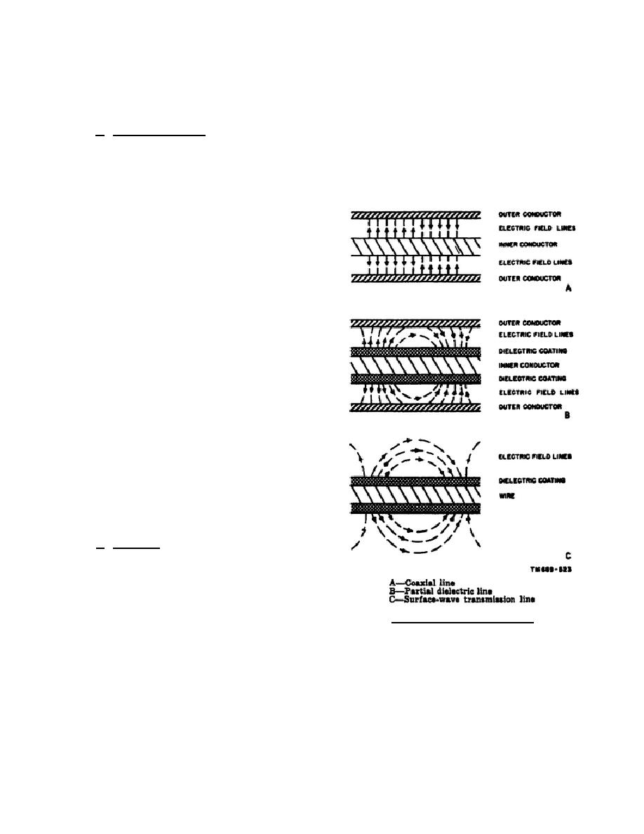
b. Wave Development. The functioning of the SWTL is best understood if it is compared with a coaxial
line, to which it is closely related. The guided wave is a transverse electric and magnetic wave that propagates
with the velocity of light (A, fig. 102). If the space between the inner and outer conductors is filled with a
dielectric material, the wave is unchanged, but the velocity of transmission is reduced. If the inner conductor is
covered with a dielectric that only partially fills the space, the velocity will be somewhere between that of a solid
dielectric and an air-filled line. An important modification of the electric field occurs as shown in B of figure
102. The field lines become curved and some of
them no longer reach the outer conductor. If the
diameter of the outer conductor is increased while
the inner conductor and its dielectric sheath are
unchanged, less of the return current reaches the
outer conductor. If the outer conductor is large
enough, conduction current along the outer
conductor becomes practically zero. Thus, the outer
conductor becomes unnecessary (C, fig. 102). To
form a practical transmission line, this mode must be
the only mode on the line which becomes excited. A
method of exciting this single mode is to start from a
coaxial line section, the inner conductor of which
has a dielectric coat, and gradually increase the
diameter of the outer conductor until it is so large
that it has no appreciable effect on the field. This is
illustrated in figure 103. In this manner, a wave on a
coaxial line is gradually changed to a guided wave
on a SWTL. The gradual expansion of the outer
conductor is done by a waterproof, cone-shaped unit
called a launcher. The dielectric cover of the wire
extends only to the tip of the launcher where the
wire enters, and no cover is needed on the line in the
taper section.
c. Line Loss. As the outside of the coaxial
cable is enlarged while keeping the same center
conductor,
Figure 102. Field distribution.
344 L2
96


 Previous Page
