d. Red differential skew control is accomplished by feeding a negative or
positive voltage to the red skew generator. The Red skew generator, in turn, feeds
the master sawtooth generator, a sawtooth waveform, at a vertical rate. This
voltage is added to the master sawtooth waveform and horizontal skew is obtained.
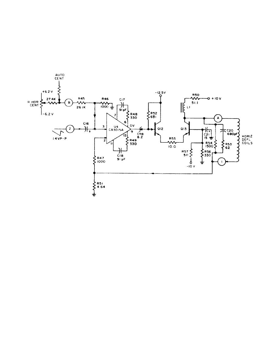
e. The red horizontal deflection amplifier can be easily described by
referring to the circuit diagram of the Red horizontal deflection amplifier (fig 2
2).
Figure 22. Red horizontal deflection amplifier, Sch Dia
f. The master sawtooth waveforms with the added differential corrections are
applied to the horizontal deflection amplifiers located on the deflection amplifier
module. These amplifiers are basically differential input operational types which
compare the deflection current samples with the applied deflection waveforms.
Precise tracking of reference and applied current are obtained through this circuit.
6. Vertical Deflection System (fig 23 foldout located at the end of Lesson 3).
Vertical deflection starts with vertical drive pulses which are obtained from the
Camera Pulse Module at a negative level. The first stage input transistor, Q22,
isolates the external drive signal from the module and prevents excessive loading
of the drive signal.
a. The drive signal feeds Q8 which discharges a capacitor that is charged by
current source Q7. Emitter follower Q9 prevents loading of the capacitor charging
circuit, thereby maintaining sawtooth linearity. The time constant of this circuit
has been chosen to provide exceptional linearity characteristics.
14


 Previous Page
