a. In order to measure the resistance of resistor XY in Figure 1-3a, the
resistor XY must be disconnected from the remainder of the circuit.
b. Then the ohmmeter is placed across the resistor as shown in Figure 1-3b.
5.
For convenience, more than one electrical measuring device may be combined in
one instrument.
An instrument of this type is variously called a multimeter, a
multitester, a voltohmmeter, etc. The term meter is frequently used in scientific
literature and may designate any of the above.
NOTE: The combination meter will be discussed later in this
section.
6.
Meter Circuitry. You may recall that you connect ammeters in series in that
part of the circuit where the current is to be measured.
The voltmeter must be
connected in parallel with the component between the two points where a potential
difference is to be measured.
The ohmmeter must not be connected into a hot
(power-source-applied) circuit.
a. Ammeter.
If you connect a 0-to 10-milliampere meter coil in a circuit
carrying 10 amperes, not only is the meter coil incapable of measuring such large
values of current, but it will be severely damaged.
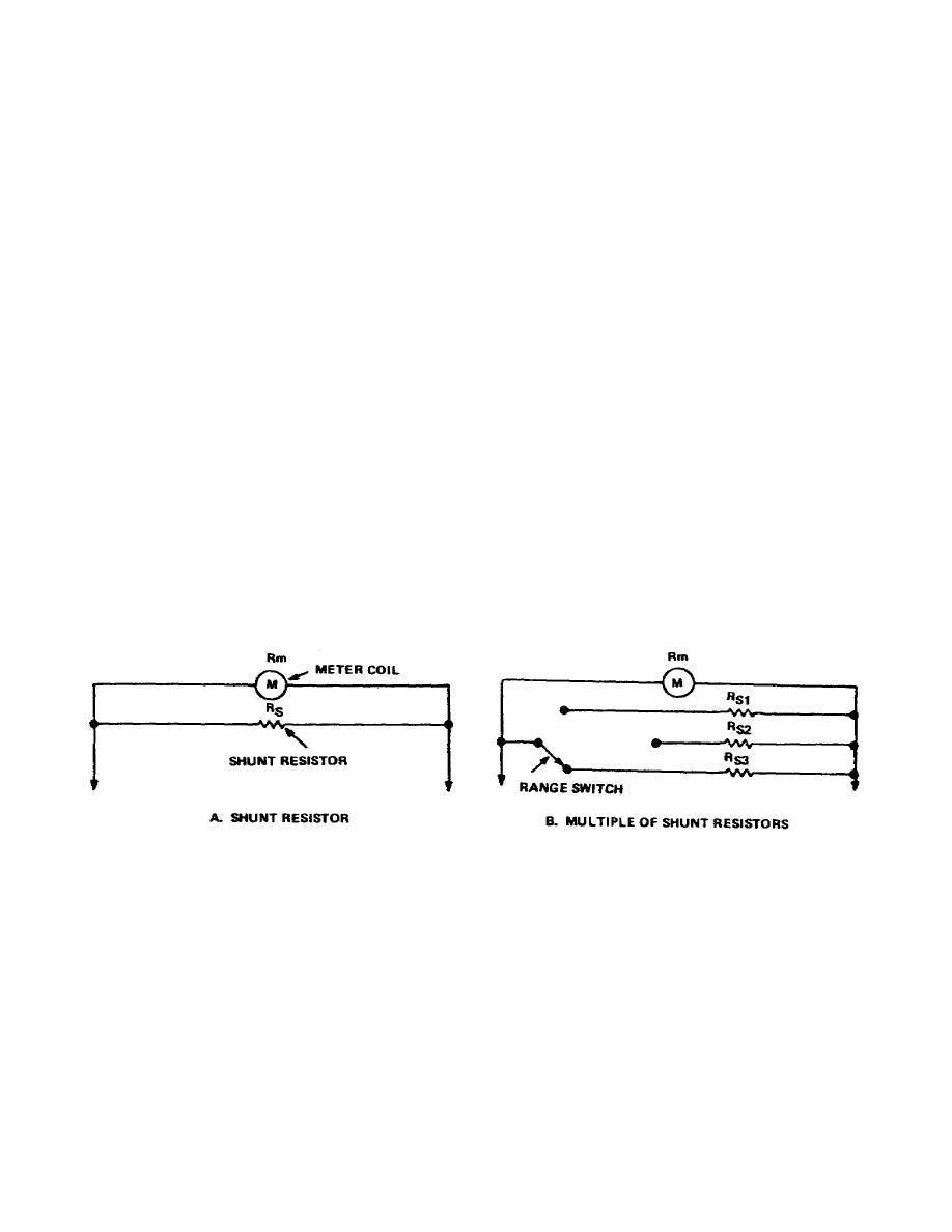
(1) To measure larger amounts of current than the coil itself can safely
carry, you connect a resistance in parallel with the coil, as shown in Figure 1-4a.
The current being measured divides between the coil and resistor, with a small
portion flowing through the coil (Rm) and the remainder through the parallel
resistor, called the meter shunt (Rs). The shunt may be built into the meter or it
may be mounted externally.
Figure 1-4.
Typical ammeter circuit
4


 Previous Page
