(2) Ammeters which are designed to measure several ranges of current use a
shunt for each range.
The shunts are mounted on a common terminal board and are
connected to a multiple switch, as shown in Figure 1-4b. Setting the switch to the
desired range connects the proper shunt into the meter circuit.
Shunts usually
contain only a fraction of an ohm of resistance and consist of a few inches of a
metal alloy having a low temperature coefficient. The alloy is drawn into a wire
and is wound around a piece of mica or fiber and mounted on a terminal board.
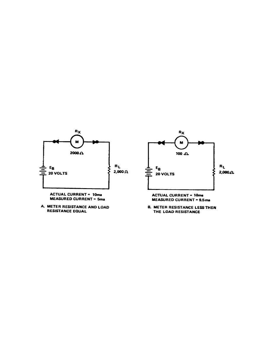
(3) The accuracy of an ammeter reading depends upon the relative magnitudes
of the meter resistance and the circuit load resistance (resistance of the circuit
into which the meter is connected).
For example: if the meter resistance (Rx)
equals the circuit load resistance (RL), as shown in Figure 1-5a, the value of
actual circuit current is twice that of the measured current, representing an error
of 50 percent. If you decrease the meter resistance as shown in Figure 1-5b, you
also decrease the percentage of error.
If the meter resistance is considerably
smaller than the load resistance, the percentage of error becomes so small that for
practical measurements it can be disregarded.
Thus, for any given circuit
conditions, the accuracy of the ammeter reading is greater if the total meter
resistance is much less than the ohmic resistance of the load.
Figure 1-5.
Error in ammeter readings
5


 Previous Page
