the portion of the circuit in which voltage is being measured.
If you observe
these precautions when using an ammeter or voltmeter, you can obtain reliable
results from these instruments.
5.
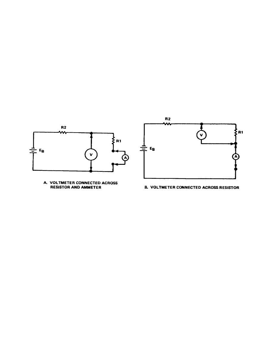
time, there are two possible ways to connect them, but each produces an error.
a. If the meters are connected as shown in Figure 1-11a, the voltmeter reads
the voltage across the resistor and the ammeter.
b. If the meters are connected as shown in Figure 1-11b, the ammeter reads
the current through the resistor R1 and the voltmeter.
c. Both methods further emphasize the fact that the resistance of the ammeter
must be very low to keep the voltage across it small, and that the resistance of a
voltmeter must be large enough to keep the current through it small.
Figure 1-11.
Measuring current and voltage simultaneously
6.
In either of the above cases, the correct connection to use is the one
leading to the least error and that depends on the relative values of resistance.
If the resistance of the circuit is small (approaching the resistance of the
ammeter), use the second circuit (fig 1-11b). If the resistance of the circuit is
large compared to the voltmeter resistance, use the first circuit (fig 1-11a). For
intermediate
values
of
circuit
resistance,
either
circuit
connection
is
satisfactory.
7.
You can determine the resistance of a circuit element by first measuring the
current through it with an ammeter, then the voltage across it with a voltmeter,
and finally apply Ohm's law.
It is much more practical, however, to use an
ohmmeter from which you can read resistance directly from a scale.
8.
When using an ohmmeter to measure resistance, proceed as follows:
11


 Previous Page
