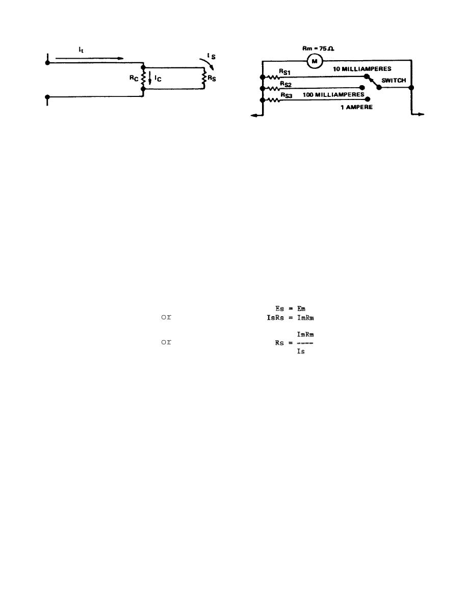
Figure 1-13.
Shunt resistor
current range
Figure 1-14.
Determining shunt
resistors
(3) Calculations such as those involved in this example enable you to
determine the size of the shunt required to extend the range of an ammeter.
Although in actual practice you seldom make these calculations, you must know how
meters having the same movement are constructed with different ranges, and how a
range switch on the same meter changes the current range of the meter.
(4) Assume that you want to make an ammeter with the ranges of 0 to 10
milliamperes, 0 to 100 milliamperes, and 0 to 1.0 ampere, as shown in Figure 1-14.
Also assume that the meter sensitivity is 1 milliampere and the coil resistance is
75 ohms.
(5) You can determine the values for Rs1, Rs2, and Rs3 since the shunt and
meter form a simple parallel circuit. As you know, the voltages across the shunt
and meter are equal, as in the following formulas:
(6) Where Rs is the shunt resistance, "Is" is the current through the shunt
at full-scale deflection, Rm is the coil resistance, and Im is the current through
the coil for full-scale deflection. Thus, the shunt resistance required to produce
the ammeter shown in Figure 1-14 are 8.33 ohms, 0.758 ohm, and 0.0751 ohm
respectively.
4.
In constructing a voltmeter with various ranges, you
must
determine the size of the multiplier to place in series with the meter coil.
15


 Previous Page
