a. The accuracy of matrix and phase adjustments in encoders may be readily
checked by comparison of the color bars signal with the output of such a device
when the signal is applied to the encoder inputs.
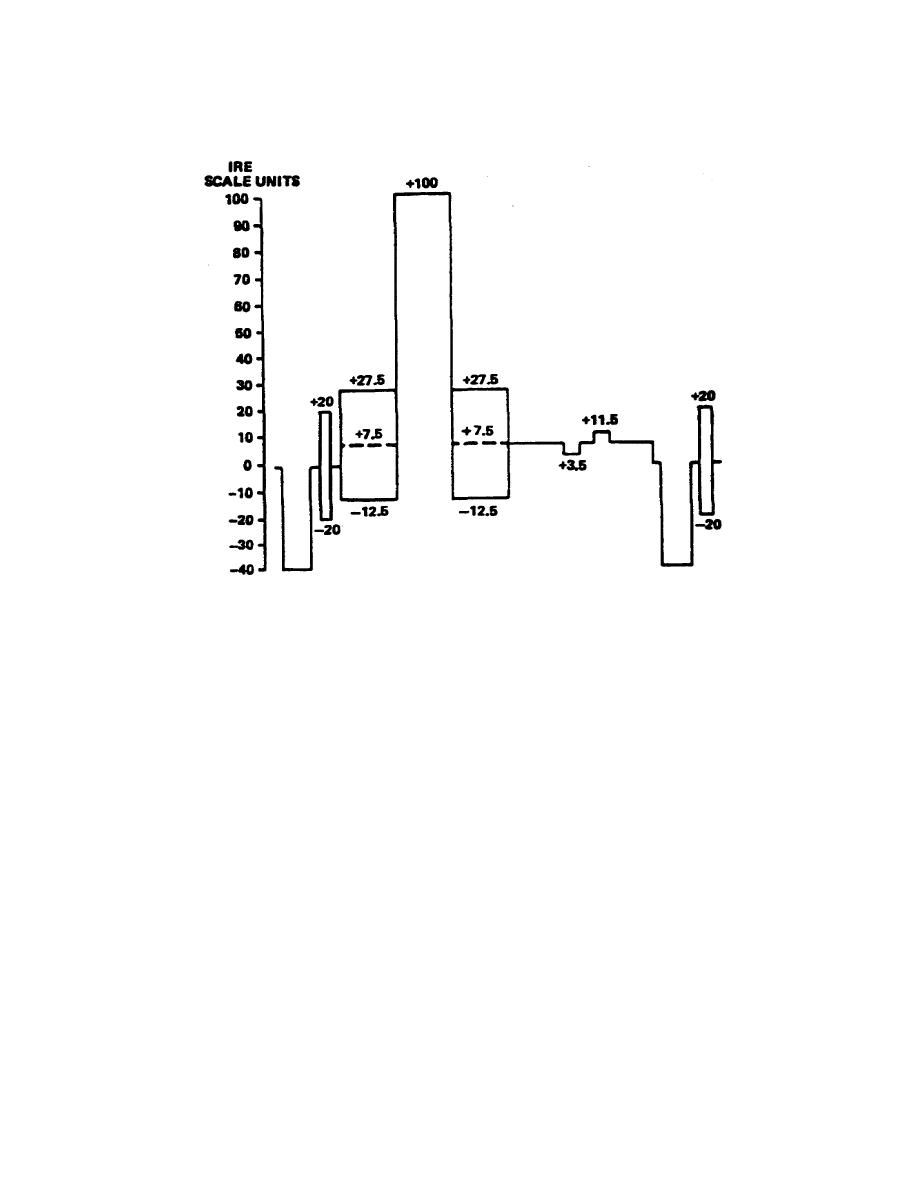
Figure 2-5b.
One line of black set signal
b. The color bars signal embodies several convenient reference relationships
that facilitate its use. The relative amplitudes of all signal components can be
checked by direct observation of the complete waveform on a television waveform
monitor.
A waveform monitor should display the relationships a, b, and c,
illustrated in figures 2-6 and 2-7.
(1) The positive peak levels of the yellow and cyan bars are nominally equal
to reference white level.
(2) The negative peak level of the green bar is nominally equal to reference
black level, when 7.5% setup is used
(3) The negative peak levels of the red and blue bars are nominally equal (-16
IRE).
c. The relative phases and amplitudes of the chrominance portion of the signal
are generally checked by observation on a vectorscope.
The quadrature phase
relationship between I and Q components of the encoded signal can be conveniently
checked by observation of the -I and Q signal axes (fig 2-8).
36


 Previous Page
