b. The window permits detecting low-frequency distortion, which has practically
no effect on the sin2 pulse.
The window shows undershoot, overshoot, and
horizontal tilt, depending on the time constant of the impairment. When used with
the sin2 pulse, the window has the same rise time as the pulse so that no
frequencies higher than the system test reference are introduced.
6.
Ringing.
a. Ringing occurs at the frequency at which the gain dip occurs in the system
being measured.
The ringing amplitude depends on the sharpness of this gain-dip
characteristic.
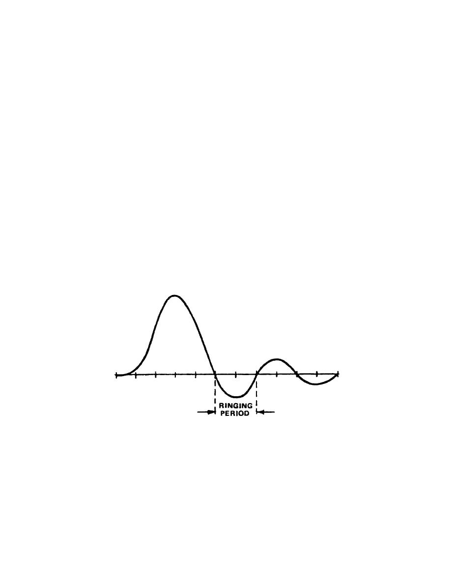
b. The ringing period (fig 3-19) is defined by the following relationship:
Rp = 1/fc
where fc is the cutoff frequency.
For example, if we have a 4-MHz cutoff, the ringing period (Rp) is:
Rp = 1/4(10 to the 6th power) = 0.250 microseconds
To find the cutoff frequency for a given measured ringing period:
fc = 1/Rp
where fc is the
cutoff
frequency
in
megahertz,
Rp
is
the
ringing
period
in
microseconds.
Figure 3-19.
Ringing period
7. Waveform Distortion.
Certain terminology is becoming standard, when defining
waveform distortion, and following is a brief review of this terminology.
a. Short-time Waveform Distortion (SD) involves
impairment
of
small
picture
detail in the horizontal direction. It is seen
67


 Previous Page
