be measured by reducing the test signal input to one-half the normal input level,
or about 0.5 volts peak to peak.
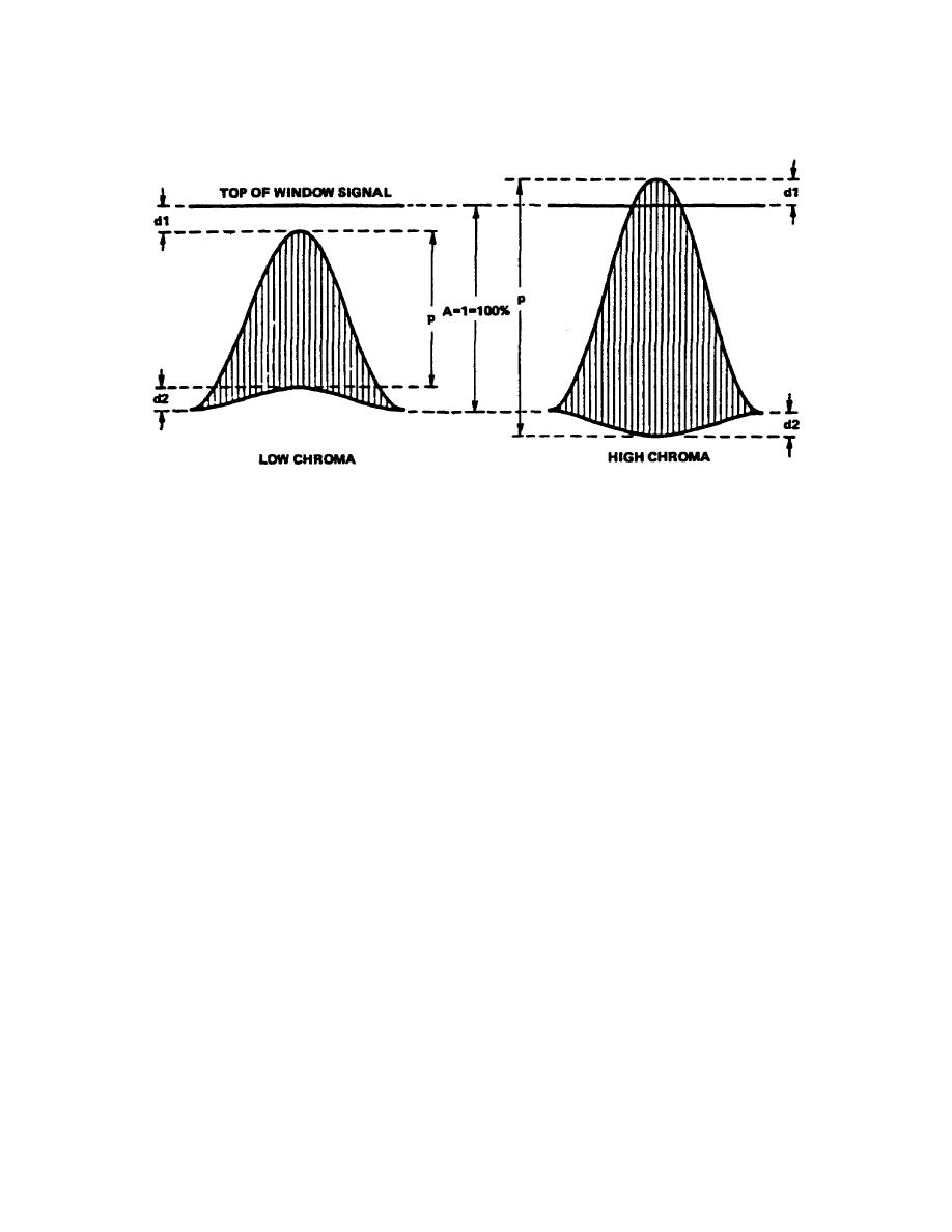
Figure 3-21.
RCL only, no phase distortion
a. Dimension p (fig 3-21) represents the peak-to-peak level of the 3.58-MHz
signal. Therefore (assuming dl and d2 are equal), RCL = p. Thus, assuming p is 80
percent, RCL is 80 percent, or simply 0.8.
b. Figure 3-22 typifies RCT (without amplitude distortion). The envelope of the
line 3.58MHz subcarrier has a sinusoidal baseline distortion indicating a delay
(fig 3-22A). The sinusoidal base-line distortion indicates an advance (fig 3-22B).
Although dimension d can be expressed as a percentage of A, the scope display does
not provide a very convenient method of specifying the actual group delay in
nanoseconds.
The maintenance technician normally is interested only in the fact
that he has a delayed-chroma or advanced-chroma problem, not in the measurement of
actual delay.
When this measurement must be determined, a calibrated variable
chroma delay or advance is used at the generator output and is adjusted for a flat
base line. The degree of RCT (delay or advance) can then be read directly from the
calibrated dial in nanoseconds.
Otherwise, RCT may be specified in terms of
whether chroma is delayed or advanced, and the percentage of d to A.
c. It is often the case that RCL and RCT distortion occur simultaneously.
Figure 3-23 represents typical displays.
The figure is self-explanatory if the
preceding two figures are understood.
70


 Previous Page
