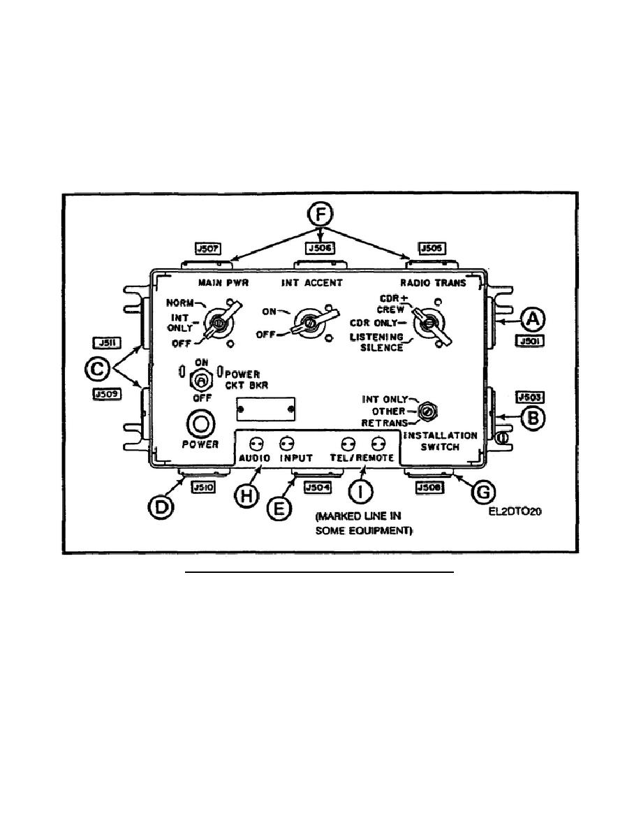
for a retransmission control box for certain radio installations. Jack J510 (D) provides connection of
audio signals for a B receiver. Jack J504 (E) provides intercom and radio Interface to the commander's
control box. The commander's C-2298 is independent of all other control boxes. The commander's
control box cable CX-4723 should always be connected to J504. Jacks J505, J506, and J507 (F) provide
intercom and radio interface to each crew member control box. Jack J508 (G) provides input power to
the AM-1780 when radios are not used. Audio input Ending posts (H) provide connection of an
additional receiver when used with radio. TEL/REMOTE(line) binding posts (I) provide a connection
for a field telephone, switchboard, or another intercom to the intercom system.
Figure 8. AM-1780 jacks and binding post locations.
m. See Figure 9, AM-1780 controls and their functions. The INSTALLATION SWITCH (A) in
the RETRANS position provides for radio relay operations. The OTHER position provides power and
controls signals when the intercom is used with radio. The INT ONLY position provides DC power
input through jack J508 when the intercom is not used with radio. The POWER CKT BKR switch (B)
provides overload protection and controls DC power input for the intercom set. The POWER lamp (C)
indicates when power is or is not being applied to the system. The MAIN PWR switch (D) OFF
position removes the DC input power from the system. The INT ONLY position applies power to the
intercom only. The NORM position provides power to the intercom and radio set when radio is used
with intercom. In the LISTENING SILENCE position of the RADIO TRANS switch (E), no crew
member can key (transmit on) the radio through the
9


 Previous Page
