
Learning Event 2:
IDENTIFY AN OR GATE AND THE INVERTER COMBINATION
1.
Adding an inverter to the output of an OR gate is a widely used technique for varying the basic
functions of OR and NOT. The OR-inverter combination is so useful that it has been given a name of its
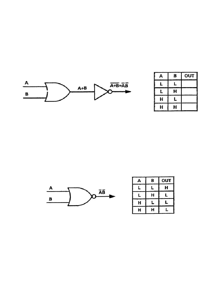
own -- NOR gate. The OR gate, Figure 2-1, performs an OR function of the input signals and the
inverter negates or "nots" the results. Hence, the name NOR (NOT OR). On a separate paper, complete
the truth table in Figure 2-1 for the output of the inverter. Compare your results with Figure 3-17.
Figure 2-1. OR gate and inverter
2.
A single circuit, and a single symbol to represent it, will also perform a NOR function: the
symbol is shown in Figure 2-2. Compare the Boolean expression at the output of the gate with the
output expression in Figure 2-1; they are identical and the function is also identical.
3.
According to the rules for state indicators, the gate in Figure 2-2 produces a low if any input is a
high. Thus, to obtain a high output both inputs must be low; it produces a high out when neither A or B
is a high.
Figure 2-2. NOR gate symbol and truth table
4.
Compare the truth table for the NOR gate in Figure 2-2 with the truth table you completed for
Figure 2-1. They are the same which proves the symbols represent circuits that perform the same
function. Do not, however, associate the circle on the output of the NOR gate with an independent
inverter. The circle does not represent an inverter, it is only a state indicator. The NOR circuit inverts
the signal. It is not an OR gate followed by an inverter.
12

 Previous Page
