Learning Event 3:
IDENTIFY AN AND GATE AND THE INVERTER COMBINATION
1.
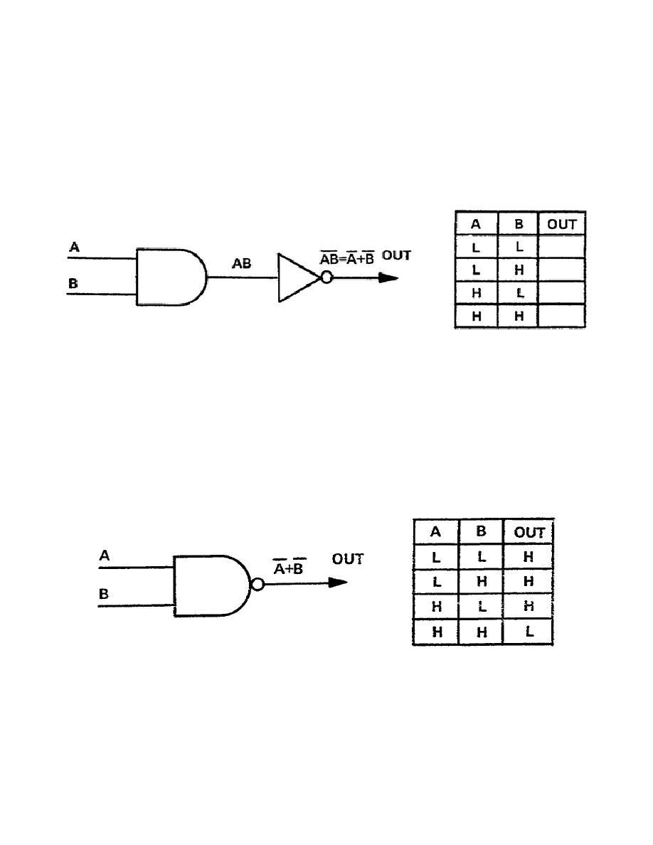
Connecting an inverter to the output of an AND gate, Figure 2-3, produces another function that
is very useful. The function is NOT AND, commonly called NAND. The function is NOT AND
because the AND gate performs and AND function of the input signals, then the inverter negates or
"nots" the result. On a separate paper, complete the truth table in Figure 2-3 for the output of the
inverter. Compare your result with Figure 2-2.
Figure 2-3. AND gate and inverter
2.
The NAND function is so often used in equipment that, like the NOR gate, it has its own symbol:
an AND gate symbol with a state indicator circle on the output and no indicators on the inputs as in
Figure 2-4. But, because the function is the opposite of AND, it is called NOT AND. Compare the truth
table in Figure 2-4 with the one you completed in Figure 2-3; they should be identical. Thus, with the
proper use of the state indicators, we have a single symbol to represent the inverter AND function. A
complete description of the operational characteristics of the gate is: all highs in, a low out; and low in,
a high out. Another way of stating the NAND function is that the circuit produces a high output if the
inputs are NOT ANDed (not both high).
Figure 2-4. NAND gate symbol and truth table
13


 Previous Page
