Lesson 1/Learning Event 5
a. Purpose. The M lead is for signaling from the switchboard toward
the SF unit, and the E lead is for signaling from the SF until toward the
switchboard. One advantage of such a system is the ease with which the E
and M (E&M) lead signals can be adapted to many types of trunk equipment.
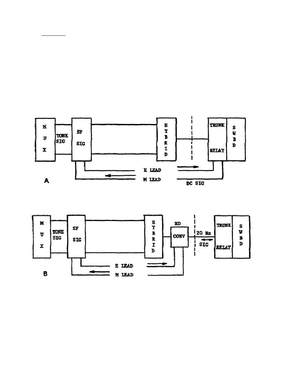
The basic layout is shown in A of figure 1-7. In this configuration the
E&M leads are extended directly into the switchboard trunk relay set, and
all in and out signaling is accomplished by the DC signals on these lines.
The SF is a two-section unit that serves both the send and receive lines
in the 4W circuit connected to a channel of a multiplexing terminal
(telephone carrier terminal). If the switchboard uses ringdown signaling,
an additional converter is needed to convert E&M lead DC signals to 20 Hz
ringing signals, as shown in B of figure 1-7.
Figure 1-7.
E&M Signaling Arrangements.
17


 Previous Page
