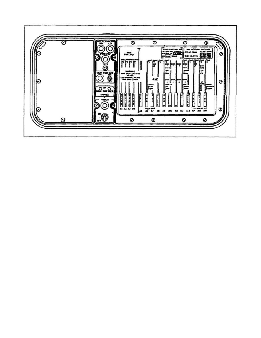
Figure 1-30. Circuit card location.
51.
Operational requirements.
a. Ground the equipment immediately.
b. Ensure all switches are off.
c. Connect the CX-11230A/G to the rear of the TD-1234/TT. It is connected to HIGH GROUP
if going to the next unit or to the terminal AN/TRC-173. It is connected to LOW GROUP if it is going
down to another TD-1234/TT or a TD-1233/TT. (See Figure 1-27.)
d. Collect power to the TD-1234/TT. Place main POWER switch in the ON position. The
power lamp lights. After a 5-second warmup, all alarm lamps should be off.
e. Connect the TS-3647/G and test the order wire system. It is connected to the ORDER
WIRE HIGH GROUP if it is going to the AN/TRC-173, or to the ORDER WIRE LOW GROUP if it is
going down to another TD-1234/TT or TD-1233/TT.
f. Perform a built-in test equipment (BITE) test. Press and release the ALARM TEST switch.
All fault and alarm lamps on the front panel and on CCAs A6 through A16 are operational.
g. If a fault is detected, turn the main POWER switch to OFF. Reset the CCA. Turn the main
POWER switch to ON. If the fault is not resolved by resetting the CCAs, you should replace the entire
unit.
SS0441
1-34


 Previous Page
