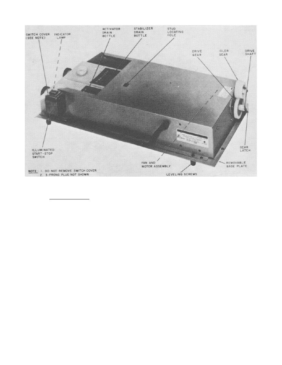
FIGURE 3-2.
Base assembly.
c. Solution tray. The plastic solution tray (figure 3-3) is mounted on
the base assembly and positioned by locating studs fitting into a stud
locating hole (figure 3-2) at the top of base. The solution tray (figure
3-3) contains two plastic drain bellows which fit into the activator and
stabilizer drain bottles, respectively.
The drain bellows are compressed
manually to empty the contents of the solution tray into the drain bottles.
185


 Previous Page
