SS0607-8
30 September 1988
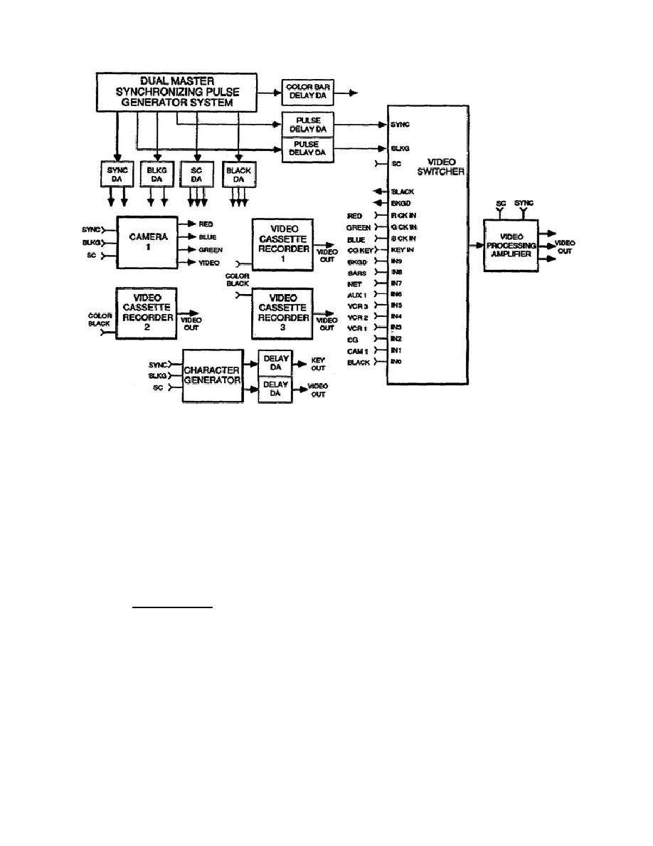
Figure 2-1.
Cumulative delay timing system
7.
The sources in this system that are to be mixed, keyed or wiped with
the video switcher must be exactly in time at the switcher input. Hence,
the obvious point of reference for this system is at the switcher input.
This point is therefore designated the zero timing point, or time zero.
8.
In Figure 2-2 the timing requirements of the equipment are plotted
relative to time zero.
9.
Camera 1 has 850 ns delay from its composite sync input to its
composite video output, and represents the longest signal path of any source
device in the system.
The character generator, switcher, and color bars
will need delay added to make their total delays the same as the camera.
Since the camera has the longest path, the pulse drives will be provided
directly from the sync generator so that the camera gets the most advanced
pulses.
The camera has a subcarrier phase control for color timing
adjustment.
The Camera 1 output becomes the reference input at the
switcher.
10. To make the video switcher internal color black and the color
background generator synchronize with the camera, both sync and blanking
drives must be delayed to the switcher by 400 ns. This is accomplished with
two adjustable pulse delay distribution amplifiers.
The switcher has a
subcarrier phase control for color timing adjustment.
13


 Previous Page
