SS0607-8
30 September 1988
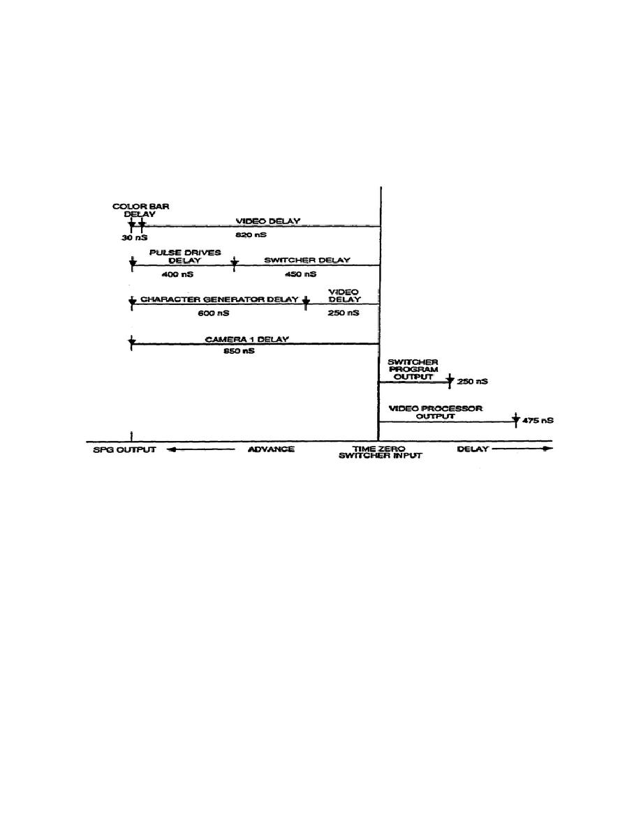
11. Timing of the character generator can be handled in two ways. Delay
can be introduced either in the pulse drives, or in the video and key
outputs of the character generator.
In this system, video delay
distribution amplifiers are added to the character generator video and key
outputs.
This method provides six timed outputs.
The amount of delay
necessary is 250 ns as shown in the illustration in Figure 2-2.
Figure 2-2.
Timing requirements relative to time zero
12. The last source to be timed are the
color bars from the master sync
generator. The color bar output is 30 ns
later than the sync output from
the sync generator. With the camera as a
reference, we can calculate that
820 ns delay to the color bar output is
required to match the camera's
delay.
13. The sync and subcarrier (required as external reference inputs for the
video processing amplifier) should come from the distribution amplifiers
feeding the switcher. The video processing amplifier has sufficient timing
range for both sync and subcarrier.
14. The sync generator is a known SC/H phased source, and the color bar
output will be SC/H phase correct. Accurate system timing can now begin by
adjusting the color bars and the camera.
Measurements are made at the
switcher output by selecting between the reference source and the source
under adjustment on the switcher. An externally locked waveform monitor and
vectorscope should be connected to the switcher output.
14


 Previous Page
