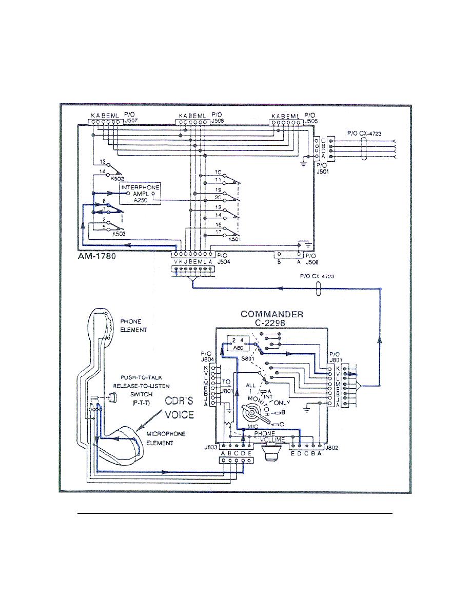
(2) When the C-2298 MONITOR switch is set to the C position (Figure
10), the voice signal is applied to pin V of J801 or J804. This signal then
goes through the CX-4723 to pin V of J504 on the AM-1780. From pin V of
J504 the signal passes through contacts 6 and 1 of K503 to the input of the
A250. (Trace this circuit on your system diagram.)
Figure 10.
Commander's voice signal, MONITOR switch set to C.
13


 Previous Page
