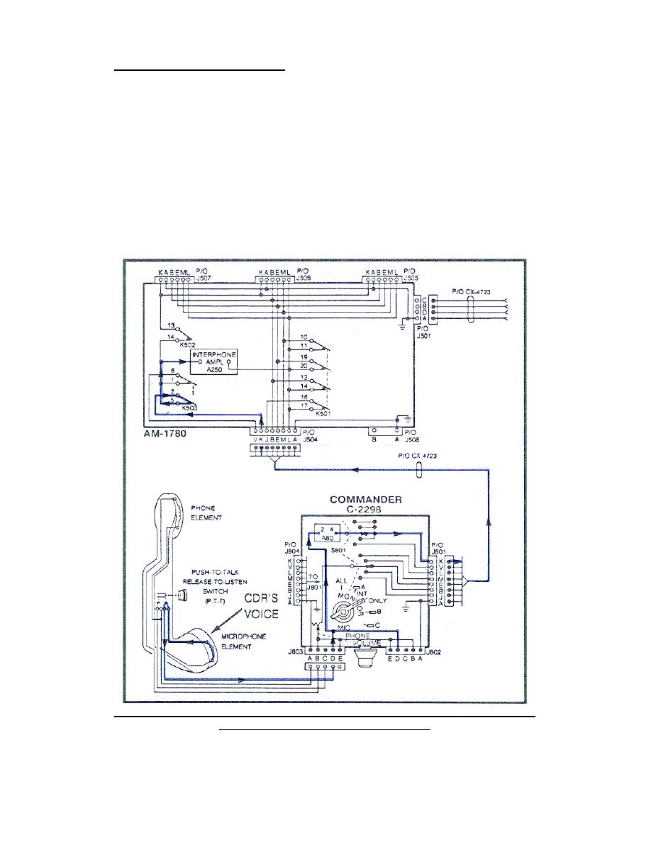
a. Commander's talk circuit. When the commander presses and holds the
handset key switch and speaks into the handset microphone (Figure 9), this
voice signal passes through the handset cable talk circuit to pin D of J803
on the CDR C-2298. From pin D of J803 this voice signal goes to the A80, in
on contact 2 and out on contact 4, to the MONITOR switch. At the MONITOR
switch, the CDR voice signal can take one of two paths, depending on the
MONITOR switch position.
(1) When the MONITOR switch is tuned to ALL, A, INT ONLY, or B, the
signal is applied to the MONITOR switch circuits, pin K of J801 or J804.
The voice signal is then passed through the CX-4723 to pin K of J504 on the
AM-1780.
The voice signal is then passed from pin K of J504, through
contacts 2 and 5 of K503, to the input of the A250. (Trace this circuit on
your system diagram.)
Figure 9.
Commander's voice signal path with MONITOR switch
set to ALL, A, INT ONLY, or B.
12


 Previous Page
