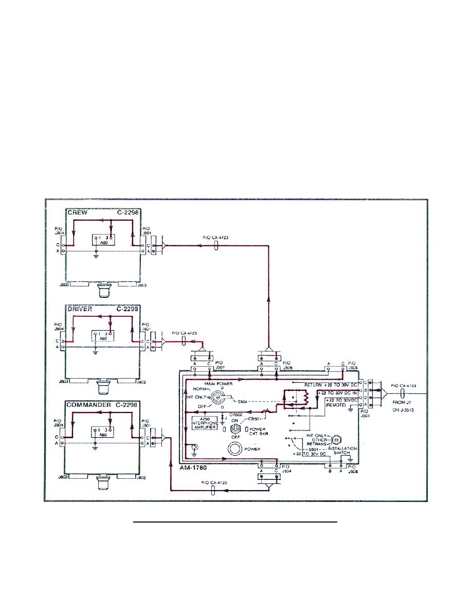
d. Voltage from pin B of jack J7 on the J-3513 is applied through the
CX-4723 cable to pin B of jack J501 on the AM-1780 (Figure 4). With the AM-
1780 MAIN POWER switch set at INT ONLY, voltage is applied from pin B of
J501 to the AM-1780 MAIN POWER switch S504.
Then, from S504 to CKT BKR
CB501 and the A250 interphone amplifier (providing the A250 with its
operating voltage). Voltage is also applied from the A250 tiepoint to the
power lamp and to pin C of J504, J505, J506, and J507. Pin C of J504, J505,
J506, and J507 apply voltage through their CX-4723 to pin C of J801 on each
C-2298 control box. From pin C of each C-2298, voltage is applied to each
A80 audio amplifier and to pin C of J804.
(Trace these circuits on the
system diagram.)
NOTE:
The MAIN POWER switch S504 on the AM-1780 provides voltage control
of the system. The power CKT BKR CB501 provides circuit protection
for the AM-1780.
Figure 4.
Intercom input power circuit.
7


 Previous Page
